@Ben Mah I'll consider this, seems like a reasonable and elegant solution.
@bhjazz - It has only been a few hours but it's funny you mention that because as I've been listening for the past few days I thought to myself, "wow this thing just gets better the more you listen to it", but then dismissed that sentiment thinking I was just full of it. I'll give it some time before making any adjustments.
Thanks for the input, everyone.
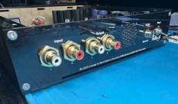
Edit: Progress pics so far. Still playing around with cooling the system and the volume pot will be mounted with a better PCB once a decision is made on the treble "issue".
@bhjazz - It has only been a few hours but it's funny you mention that because as I've been listening for the past few days I thought to myself, "wow this thing just gets better the more you listen to it", but then dismissed that sentiment thinking I was just full of it. I'll give it some time before making any adjustments.
Thanks for the input, everyone.
Edit: Progress pics so far. Still playing around with cooling the system and the volume pot will be mounted with a better PCB once a decision is made on the treble "issue".
Attachments
Last edited:
the soundstage became more coherent and accurate.
To me, there is definitely a toe-in setup that is perfect for a speaker, and every speaker is different. Too far toed out and you lose the center image, too far in and you lose the space around the recording. Somewhere in between you get both - and all the magic.

Excellent. Connect a source with Internet radio running and leave the BA2018 on for 24 hours or so. You don't even need to have your amplifiers on, either. See if this helps.I'll give it some time before making any adjustments.
Still playing around with cooling the system
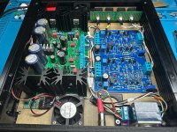
Ah, AMB Labs power supply. Nice. Does the σ22 need active cooling? I can't tell if you have any venting in the bottom or side of the chassis, so possibly you do..
Not so much soundstage necessarily, I was mainly suggesting messing with the toe-out and listening off axis due to the natural roll off on the top end that you get typically. A good way to soften the top and tune the tonal balance more to your liking.
Attachments
There is a 2mm gap at the bottom between the plexiglass mount and the aluminum chassis (the opening is the tiny slit at the bottom of the rear panel) but i don't think it's big enough for the horizontally mounted fan to suck any air in. I think I'm going to end up putting a fan at the front and rear diagonally arranged to coerce air across as much of the circuitry as possible. I've noticed the mosfet heatsinks get hot on the o22, and the big transistors on the BA2018 get hot as well. Not sure if active cooling is even warranted, as I enjoy the building process just as much as I do the final result. There is definitely a "I want it to look cool" (no pun intended) factor involved in the build.Excellent. Connect a source with Internet radio running and leave the BA2018 on for 24 hours or so. You don't even need to have your amplifiers on, either. See if this helps.
Ah, AMB Labs power supply. Nice. Does the σ22 need active cooling? I can't tell if you have any venting in the bottom or side of the chassis, so possibly you do..
Does the bottom and top plates of the chassis have cooling vents?
What is the purpose of the plexiglass mount?
I see heat sinks mounted on the PCB. The presence of heat sinks imply that air movement is necessary. For air to move, the chassis must be able to allow air flow in and out. The logical location for air inflow is at the bottom of the chassis and for air outflow is at the top of the chassis. So provide vents in the top and bottom of the chassis and that is probably enough to cool a preamp.
That's what the AMB and BA board are mounted on. So basically instead of mounting the boards on standoffs that screw directly into the chassis, I laser cut a piece of acrylic that mounts to the chassis using the screw holes the chassis already provides. The PCBs sit on top of that piece of acrylic.What is the purpose of the plexiglass mount?
I just wanted to avoid drilling and tapping any new holes into the chassis in case I want to repurpose it later.
The way it's pictured is such that the fan that's horizontally mounted (towards the bottom of the picture) pulls fresh air in through the bottom of the chassis and then the 30mm fan (towards the top of the picture) pulls hot air out. The idea was to pull air in on one end of the chassis and have it vented out through the other side, presumably allowing that air to pass through all the components in between. Although the right idea, implementation was poor.The presence of heat sinks imply that air movement is necessary. For air to move, the chassis must be able to allow air flow in and out. The logical location for air inflow is at the bottom of the chassis and for air outflow is at the top of the chassis.
I've decided to just going to cut holes into the front panel for inlet and leave the 30mm fan at the back of the chassis to pull hot air out.
Attachments

@Ben Mah I'll consider this, seems like a reasonable and elegant solution.
@bhjazz - It has only been a few hours but it's funny you mention that because as I've been listening for the past few days I thought to myself, "wow this thing just gets better the more you listen to it", but then dismissed that sentiment thinking I was just full of it. I'll give it some time before making any adjustments.
Thanks for the input, everyone.
Edit: Progress pics so far. Still playing around with cooling the system and the volume pot will be mounted with a better PCB once a decision is made on the treble "issue".
Looks great! Which psu are you using?
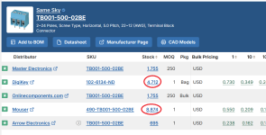
I have one of these bought off the classified and am finally getting round to get this going but its missing some Terminal blocks, does anyone have a part number for these? Its the two position ones.
What would be the best way to wire an open input on a selector switch to be a mute switch?
Can it be left open or does it need to be wired to ground? Is a resistor or capacitor neeeded?
Can it be left open or does it need to be wired to ground? Is a resistor or capacitor neeeded?
I have one of these bought off the classified and am finally getting round to get this going but its missing some Terminal blocks, does anyone have a part number for these? Its the two position ones.
TB001-500-02BE
I've built a few of these with the different transistor output options. I'm now wanting to convert one that used the less powerful output transistors to one that uses the more powerful ones (for headphones). But it appears that the KSA1220s are EOL. I had a look at a thread discussing this, but I did not see anything definite there about replacements for use in this circuit. Help! I did see some sets on EBay, which look legit, so that's an option, I guess.
But it appears that the KSA1220s are EOL. I had a look at a thread discussing this, but I did not see anything definite there about replacements for use in this circuit. Help!
I thought I remembered that more than one Forum member has posted in this thread, with specific recommendations about alternatives. Let me repeat: in this thread.
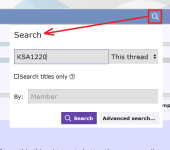
So I did the little Forum stunt shown in the screen capture below, and presto! There it was, right on the first page of search results. Give it a try yourself. Teach, fish, one day, forever, etc.
_
Attachments
- Home
- Amplifiers
- Pass Labs
- Wayne's BA 2018 linestage