Well, I'm part way there. The VRDN boards are now all grounded at the star ground and I've set up ISS board correctly. The connections between the ISS board and the BA2018 boards were air-wired to ensure I had done it right. I have eliminated the loud ground noise, but there is still some ground noise in the background. Nothing like it was before, but the build is not completely silent. At this point, I'll get the air-wired connections twisted and possibly even shielded as maybe I'm picking up some electrical or magnetic noise? If that doesn't work I suppose I'll have to start connecting even more items to star ground. I'm a bit puzzled.

I'm a bit puzzled.
I built a BA2018 preamp withe the Audio Academy Muse volume control along with a remote VRDN power supply. I had a hard time getting everything to work together regarding noise. Audio Academy was very helpful recommending additional capacitors in the 15v regulator to no avail. I shorted the De-Noizer circuit using the jumper on the VRDN PCB and have had zero issues since.
May not help, but it's easy to try.
Attachments
Will do this soon. I appreciate the extra set(s) of eyes.Post pictures of your build. Include pictures that show the whole chassis layout.
Wow, good to know. I'll throw that into the mix. Good to hear that you finally got it all working!I built a BA2018 preamp with the...
Thanks, guys!
Okay, jumpered the Denoizer circuit to no avail. Worth a try. Remote control is also acting up - codes being received but not being processed. I'll troubleshoot that as well since it could be related to the other issues and is certainly connected to the volume control and input switching system. If that all checks out (and it did when I assembled it) then I'll post pics.
As much as I enjoy Thanksgiving, I wish it were not tomorrow. More important things need to be done!
(edited)
As much as I enjoy Thanksgiving, I wish it were not tomorrow. More important things need to be done!
(edited)
Last edited:
Post pictures of your build. Include pictures that show the whole chassis layout.
Pics attached. Over the last few days I have tried a number of things, none of which have made any difference to the good old fashioned ground noise.
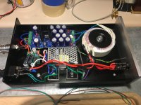
One thing that occurred to me is that the noise happens with and without the ISS board attached, and with and without that board even being powered up. So with the two BA2018 channels running with no inputs I still get noise at the outputs; this suggests to me that my problem may lie with the general power system. The Antek AS0518 purple wire has been connected to chassis ground as seen on the photos, but did I miss something else in the transformer installation? Seems to be a rather straightforward thing to do.
The three VRDNs all test correctly as much as I can tell. The VRDN for the ISS board is set at +/-15V and the two VRDN boards for the BA2018s are set at +/-18V. I did notice that directly on the VRDN boards, with no loads or BA2018 boards connected, 0V to +V showed 0L Ohm, but 0V to -V showed -1.8M Ohm. Seemed a bit odd to me, but in testing the actual output I get the specified +18V and -18V.
Finally, although they appear in the photos, the output transformers are not yet connected to anything,
I'm stumped and wishing I had a 'scope. Thanks for any help or suggestions. More pics? Just ask. thx BH
Please post a top view picture showing the whole chassis, including all four sides and their components/switches/connectors. The information is incomplete with the pictures that have been posted.
A few comments based on what I can see:
- The location of the power transformer close to the signal wires, signal transformers, and signal inputs on the back panel is problematic.
- A better location for the power transformer would be at the front left corner of the chassis, and run the AC wires against the left side of the chassis to the power transformer.
- Locate the signal transformers as far away from the power transformer as possible.
-After relocation, rotate the power transformer to find the orientation that produces the least amount of noise.
-After relocation, a transformer shield or steel sheeting to shield the power transformer from the rest of the components may be helpful. An alternate would be to place a steel sheet between the power transformer/power supplies and the audio components. Hopefully though shielding will not be needed.
-Check that the screws attaching the PCBs to the chassis are not shorting the Ground on the PCB to chassis.
Last edited:
Hello bhjazz,
I fully agree with the tips from Ben Mah.
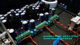
You could also try a groundloopbreaker. You put a 5 Ohm to 10 Ohm -resistor between the black groundwire (coming from the BA2018 pcb) to your ground on the VRDN-board. Use resistors of minimum 1 W. Do this on both channels. Can be done / checked fast.
Greets
Dirk
I fully agree with the tips from Ben Mah.
You could also try a groundloopbreaker. You put a 5 Ohm to 10 Ohm -resistor between the black groundwire (coming from the BA2018 pcb) to your ground on the VRDN-board. Use resistors of minimum 1 W. Do this on both channels. Can be done / checked fast.
Greets
Dirk
Attachments
I am not familiar with VRDN, but shouldn’t you connect positive and negative grounds at the output?
Edit: Never mind. It seem connected with a whole GND plane.
Edit: Never mind. It seem connected with a whole GND plane.
I would want a ground loop breaker as already mentioned.
What about the noise if only a single BA2018 is powered up? No difference?
What about the noise if only a single BA2018 is powered up? No difference?
Thanks for all the input, everyone. I appreciate it.
As for the transformer, it is an Antek AS-0518 which has a static shield between the primary and secondary windings. It's a fairly popular choice for a BA2018 build and I had not read about many issues with it. There are several BA2018 builds which use this transformer that are in very small chassis - as in the transformer is possibly 10-15cm (4-6") from the BA2018 boards - and nobody seems to have much noise. Mine is currently 22cm (8.5") from the input board, and I could get about 28cm (11") if I moved it.
All other components (ISS, front display, input jacks, etc.) were disconnected.
The chassis-mounted output jacks were also disconnected from the BA2018 boards. Instead I used alligator clips to connect the BA2018 outputs to RCA cables, then fed those to a battery-powered headphone amp. The noise remained until I put a finger on the star ground point, then 98% silence unless the amp was turned up to 11. This smells of ground loop...
I'm out of 5 to 10 Ohm 1 watt resistors, but will grab some this week and test.
Thank you thank you everyone for the comments and suggestions.
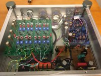
Here are more pics, as requested. First one is whole chassis, second one is the rear panel, posted for clarity. Front panel only has the display system and the power switch which only operates the Muses/ISS board. That is, when there is power connected: both BA2018 boards get power, and the Muses/ISS board will toggle on or off with a momentary contact switch. Hopefully that's clear.


I agree but this seems like a tradeoff - either isolate incoming AC to the back corner/side and run DC to the rest of the system, or run AC to the front of the chassis and have that line possibly radiating electrical field. I chose the former.- A better location for the power transformer would be at the front left corner of the chassis, and run the AC wires against the left side of the chassis to the power transformer.
I agree they could be further from the main transformer, but for my testing they are not connected.Locate the signal transformers as far away from the power transformer as possible.
Ah, this is the reason why there is a wide gap between the power supply bits and the audio side/output transformers. It's on my list if I find that there is no other fix!An alternate would be to place a steel sheet between the power transformer/power supplies and the audio components.
As for the transformer, it is an Antek AS-0518 which has a static shield between the primary and secondary windings. It's a fairly popular choice for a BA2018 build and I had not read about many issues with it. There are several BA2018 builds which use this transformer that are in very small chassis - as in the transformer is possibly 10-15cm (4-6") from the BA2018 boards - and nobody seems to have much noise. Mine is currently 22cm (8.5") from the input board, and I could get about 28cm (11") if I moved it.
Excellent idea. Checked every one, though, and all is well.Check that the screws attaching the PCBs to the chassis are not shorting the Ground on the PCB to chassis.
No difference. Good test!What about the noise if only a single BA2018 is powered up? No difference?
My last test was to only have the following in play: transformer, two VRDN regulators, both BA2018 channels.You could also try a ground loop breaker.
All other components (ISS, front display, input jacks, etc.) were disconnected.
The chassis-mounted output jacks were also disconnected from the BA2018 boards. Instead I used alligator clips to connect the BA2018 outputs to RCA cables, then fed those to a battery-powered headphone amp. The noise remained until I put a finger on the star ground point, then 98% silence unless the amp was turned up to 11. This smells of ground loop...
I'm out of 5 to 10 Ohm 1 watt resistors, but will grab some this week and test.
Thank you thank you everyone for the comments and suggestions.
Here are more pics, as requested. First one is whole chassis, second one is the rear panel, posted for clarity. Front panel only has the display system and the power switch which only operates the Muses/ISS board. That is, when there is power connected: both BA2018 boards get power, and the Muses/ISS board will toggle on or off with a momentary contact switch. Hopefully that's clear.
The Antek power transformer radiates a stronger field than the twisted AC wires. That was the reason why I also suggested rotating the transformer as it seems to me that Antek transformers radiate a stronger field from the points where the leads exit the transformer. You can temporarily relocate the power transformer outside of the chassis as a check.I agree but this seems like a tradeoff - either isolate incoming AC to the back corner/side and run DC to the rest of the system, or run AC to the front of the chassis and have that line possibly radiating electrical field. I chose the former.
My last test was to only have the following in play: transformer, two VRDN regulators, both BA2018 channels.
All other components (ISS, front display, input jacks, etc.) were disconnected.
The chassis-mounted output jacks were also disconnected from the BA2018 boards. Instead I used alligator clips to connect the BA2018 outputs to RCA cables, then fed those to a battery-powered headphone amp. The noise remained until I put a finger on the star ground point, then 98% silence unless the amp was turned up to 11. This smells of ground loop...
Yes, sounds like a grounding issue. Did you short the audio inputs? Did you try it with a different amplifier? It's a good idea, just to be sure that a different combination of preamp and amp also shows the same issue.
If you have some lower wattage resistors you can still try the resistor ground lift. If there is no fault that causes high current to ground then a lower wattage resistor. Or you can combine some resistors to equal approximately 10R and a total higher wattage. Keep the same minimum setup with only the transformer, regulators, and preamp channels. Place the ground lift resistors between the regulators' output ground and chassis ground.
looking at the overhead shot...
are the two halves of each VRDN connected together at ground?
looking at the wiring one side is connected to the gain stage and the other to the chassis. is that a problem?
are the two halves of each VRDN connected together at ground?
looking at the wiring one side is connected to the gain stage and the other to the chassis. is that a problem?
I'm blown away. You guys are awesome! 🙂
I'll try all of these suggestions, but in short:
Ben: spot on as usual (!) and I will test more amplifiers. The amp I used was critical to me since it is battery powered.
Your comment re: Antek now makes sense. Very interesting.
Craig: Yes and yes.
mhenschel: yes, the ground plane is connected to both sides of the PCB.
I have seen ground loop breakers with a 0.1µF cap in parallel. I'm not completely clear about why this might help but is there any reason why I wouldn't want to do the same?
Last edited:
I may have to head that way, mhenschel...
To note: Ben, great ideas from you: don't forget to short the inputs and try a different headphone amp. Both of those helped in tonight's diagnosis. Thank you for calling those out.
So tonight's testing was with a couple of 5W 5 Ohm resistors wired up just like cubicincher had described. Crazy oversized for the task but found them easy enough at the local parts joint.
Right channel, run alone, wow, finally quiet. Add in another resistor to the left channel, power it up and...noise returns to both channels. So geez, there is some dark voodoo going on when two or more VRDNs are up and running. Will ponder off into the darkness...I'm still missing something.
Last edited:
I'm unfairly calling out the VRDNs! It just occurred to me that when I powered up the left channel with the next VRDN, okay, sure, the noise returned to both channels. But what I did learn is that the resistor connecting that second regulator to the star ground - it seems to have done nothing. I pulled it out of it's connection while powered up and there wasn't even the slightest change in sound. To me, it's probably doing nothing. Weird. When the noise returned to both channels with a second power supply attached...hmm. Perhaps those resistors that are going to the star ground could be duplicated from the regulators to the BA2018 boards. More to do.
- Home
- Amplifiers
- Pass Labs
- Wayne's BA 2018 linestage