re: Bleeder - 2k2 3W is fine. 4k7 is also fine; just a little slower to bleed the caps. Some people leave them out all-together, I happen to like the assurance (and visual indication from the LEDs) that my caps in my PSU are mostly bled before attempting service. YMMV.
re: using the 0R47 (recommended) R in the CRC - Yes, use them.
These folks do a very nice job, IMO, of choosing parts and building this board for a typical First Watt amplifier. Can be a nice jumping off point for your build. The PSU for the AJzm and AJ can be the same.
https://diyalephj.blogspot.com/

Hello Folks,
I am building a Wolverine amplifier, and I am trying to determine how the values of the components on the Universal Power Supply will need to change. I'll be running two separate transformers and two Universal PSU boards, one for each channel. I'll need 71 Volt rails. Transformers will each be 500 VA with dual 50 V secondaries. I'll be driving 4 ohm loads. The output devices will develop 430 watts/channel.
The Wolverine requires 35 A 400 V bridge rectifiers. Can I use a diode array one pair common cathode rated 600 V 60 A in a TO-247-3 package. Anyone familiar with the pcb will know there will be eight of these devices with heat sinks on each board.
Can I use 10,000 uF 80 V filter capacitors?
Pi (filter) resistors 2 ohm, 3 W flame proof; 8 in parallel on each board.
Bleeder resistors will be 22k 3 W.
Do I need to change the value of the output snubber caps rated at 0.1 uF, 100 V or the output snubber resistors rated at 1 ohm 3 watts.
If anyone is familiar with using the Universal PSU boards for more powerful amplifiers like the Honeybadger, I'd be interested in your input regarding whether I should consider changing any of the above values due to the higher voltage rails.
Many thanks,
John
jminassi:
I built a Wolverine integrated amplifier for my parents a couple of years ago. After I had committed to the power supply for the amp, I was advised that CRC supplies might not be ideal for Class A/B amps (see post #552 at https://www.diyaudio.com/community/...rine-build-thread.385920/page-28#post-7136806 ). I never did get a clear answer as to why that might be, but you might want to take that into consideration in your build. That said, the power supply I ended up with was a CRC design and the resistor stage included six 0.47R 5W flame proof resistors in parallel per rail. That amp sounds great.
Regards,
Scott
Scott,
Thanks for the info. I am going to re-think the PSU. I know I want to build a linear supply because if something fails down the line, I'll have a clue as to how to fix it. If a switcher fails, it goes into a landfill. Apparently the resistor in a CRC can produce a drop in current that is not good for many Class AB amplifiers.
Best,
John
Hi, Did you decide on it?Hello Folks,
I am building a Wolverine amplifier, and I am trying to determine how the values of the components on the Universal Power Supply will need to change. I'll be running two separate transformers and two Universal PSU boards, one for each channel. I'll need 71 Volt rails. Transformers will each be 500 VA with dual 50 V secondaries. I'll be driving 4 ohm loads. The output devices will develop 430 watts/channel.
The Wolverine requires 35 A 400 V bridge rectifiers. Can I use a diode array one pair common cathode rated 600 V 60 A in a TO-247-3 package. Anyone familiar with the pcb will know there will be eight of these devices with heat sinks on each board.
Can I use 10,000 uF 80 V filter capacitors?
I built the diode array you're quoting for a project of mine. It was a bit of work and in the end I found it to be of no particular advantage for my purposes. I went back to the KBPC3504T for ease of use and simplicity. If want to see some really nice PS stuff go look at Randy Thatchers offerings. He does really nice work and is a great DIY member.Can I use a diode array one pair common cathode rated 600 V 60 A in a TO-247-3 package. Anyone familiar with the pcb will know there will be eight of these devices with heat sinks on each board.
Many thanks,
John
Regards,
Dan
Check out the first post in this thread Classic Aleph Amplifier. There's some really nice power supplies there.
Regards,
Dan
Regards,
Dan
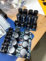
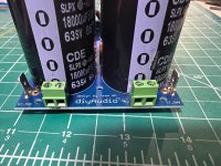
Ok guys, I'll check it out. But it's too late for this project because the power supplies are already built (see picture below). I was instructed to read Rod Elliott's treatise on power supplies. My interpretation of his advice is that for the Wolverine 80,000 uF of capacitance at 80 V per channel was more than enough, so I used eight 10,000 uF 80 V capacitors per channel (I'm building a dual power supply).
I also learned that 35 A 400 V diode bridges would be adequate. I wanted to mount the diodes on the diyaudio store PSU boards instead of using those little diode cases that mount to the chassis. There wasn't much of a difference in price between what I needed and going overkill at 60 A 600 V, so that is what I did. And yes, you have to buy heat sinks for each of them. It would have been much less expensive to buy the little diode bricks.
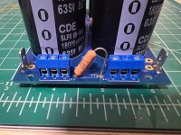
I did not get a good read on how effective a CRC filter is on a Class A/B amp versus a Class A amp. When I built the F4 I used eight 0.47 ohm 3 watt resistors.......which I now understand is hardly any resistance at all since they are wired in parallel. For the Wolverine I used four 1 ohm 5 watt resistors per power supply board and jumpered the optional resistor positions. I can always swap them out if necessary.
I used the standard input snubbers. I am not currently using output snubbers because I don't have a clue as to what the component values should be. I wish the diyaudio store would make the Quasimodo Bell Ringer available so I could figure it out as I am just about to buy a scope.
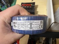
I ordered two audio grade 500 VA transformers with twin 50 V secondaries from Toroidy. I may wind up regretting this. They cleared customs on October 18 and went to the Philadelphia UPS center and then vanished. I am corresponding with Toroidy to see how to handle this. I now wish I had just ordered them from Antek.
Best,
John
I also learned that 35 A 400 V diode bridges would be adequate. I wanted to mount the diodes on the diyaudio store PSU boards instead of using those little diode cases that mount to the chassis. There wasn't much of a difference in price between what I needed and going overkill at 60 A 600 V, so that is what I did. And yes, you have to buy heat sinks for each of them. It would have been much less expensive to buy the little diode bricks.
I did not get a good read on how effective a CRC filter is on a Class A/B amp versus a Class A amp. When I built the F4 I used eight 0.47 ohm 3 watt resistors.......which I now understand is hardly any resistance at all since they are wired in parallel. For the Wolverine I used four 1 ohm 5 watt resistors per power supply board and jumpered the optional resistor positions. I can always swap them out if necessary.
I used the standard input snubbers. I am not currently using output snubbers because I don't have a clue as to what the component values should be. I wish the diyaudio store would make the Quasimodo Bell Ringer available so I could figure it out as I am just about to buy a scope.
I ordered two audio grade 500 VA transformers with twin 50 V secondaries from Toroidy. I may wind up regretting this. They cleared customs on October 18 and went to the Philadelphia UPS center and then vanished. I am corresponding with Toroidy to see how to handle this. I now wish I had just ordered them from Antek.
Best,
John
Attachments
Looking good!
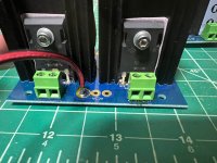
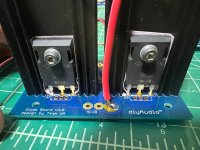
For a class-AB amplifier the R value in the CRC needs to be very low, even lower than a alass-A amp.. I'd choose something like 0.47ohm 3W resistors in all the standard and optional positions. Your (4) 1ohm resistors in the PSUs are too much R, however by jumpering the optional resistor positions you have essentially removed the resistors, (because the wires are in parallel with the resistors...) so it will not cause any issues.
Yes, the diode bridges are cheaper... but the discrete solution with heatsinks looks amazing.
Output snubber is useless, you should leave it open. However, you have stuffed the output snubber in the photos... the input snubber is the one near the diodes and is quite useful. Getting PCBs made from JLCPCB or similar is quite easy, use this as a great chance to get Quasimodo made. Or ask in the thread if anybody has a spare PCB, I bet somebody does.
I am planning a build with 71V rails (Dual mono), hence I am thinking of using 100V LPS, 80kuf per channel capacitor bank.Ok guys, I'll check it out. But it's too late for this project because the power supplies are already built (see picture below). I was instructed to read Rod Elliott's treatise on power supplies. My interpretation of his advice is that for the Wolverine 80,000 uF of capacitance at 80 V per channel was more than enough, so I used eight 10,000 uF 80 V capacitors per channel (I'm building a dual power supply).
Will this board be able to handle 100V?
Thanks for the input 6L6. That kind of information is hard to find in the audio text books I'm aware of. I must get that Quasimodo pcb. It should be obvious that I'm just an implementor way out on a limb.....I really don't know what I'm doing.
Gill.T, I believe you can use the 100 V rated capacitors without any issue, but 6L6 would be the best person to give advice here.
John
Gill.T, I believe you can use the 100 V rated capacitors without any issue, but 6L6 would be the best person to give advice here.
John
For PS caps, over-rated on voltage is better. e.g. for 24VDC rails, use 35VDC or 50VDC or higher. Desire is to have them not break down internally due to an over-voltage condition.
Hello,
I've read through the earlier bits of this thread and have a few questions. Mostly I am just trying to reassure myself that I'm hooking this up right before I do something stupid!
I have v3 of the boards. I've split the boards up into 4 individual pieces and was planning to jumper wire from the rectifier to each of the boards for dc. I have a toroid which has, as I understand it, 2 pairs of 110/US volts ac in and a 25v ac out.
The toroid I have is: https://www.parts-express.com/Avel-Y236652-250VA-25V25V-Toroidal-Transformer-122-625?quantity=1
If I understand how this works I have 2 separate inputs.
blue / gray line in goes to black / red at 25v out
violet / brown line in goes to orange / yellow 25v out
So if I only need a single 25v I could just hook up blue/gray and black/red right? I don't have to use both? Or if I want both I would hook blue/violet to black and gray/ground to white - for instance.
Then on the output from the transformer I would hook black/red to what? This is where I am a little unsure. Would I hook black to AC1A and red to AC1b? I'm not sure what to do here.
I would love it if there was a consolidated wiki with clearer instructions on how to use the board vs reading through a rather lengthy thread.
In case it helps attached is the photo from the actual toroid. I also attached views of both sides of the rectifier and dc board. I accidentally ordered the wrong size resistor - guessing thats just an overkill resistor right? 😉
Attachments
Ah interesting. Its for the amp camp amp. I don't recall what voltage the boards can support - its the stock from diyaudio. I forget the version - ordered from 2021
That transformer won't work for ACA. You need 18VAC secondaries to make 24VDC.
Yes, you can use one cap board and one diode section for a single voltage supply. Transformer connections would be primary in parallel, BLU+VIO to live, GRY+BRN to neutral. Secondary also in parallel, BLK+ORA to AC1A on the diode section, RED+YEL to AC1B.
Yes, you can use one cap board and one diode section for a single voltage supply. Transformer connections would be primary in parallel, BLU+VIO to live, GRY+BRN to neutral. Secondary also in parallel, BLK+ORA to AC1A on the diode section, RED+YEL to AC1B.
Ah ok so something like this then: https://www.parts-express.com/Avel-Y236502-160VA-18V18V-Toroidal-Transformer-122-610?quantity=1
Are you aware of other suppliers of toroids? am I going too big or is this actually what I would need? I don't have a sense of how much current the aca can pull. I kinda guessed - wrong in fact ;(
Are you aware of other suppliers of toroids? am I going too big or is this actually what I would need? I don't have a sense of how much current the aca can pull. I kinda guessed - wrong in fact ;(
Or maybe this one? https://www.amplifiedparts.com/products/transformer-hammond-toroidal-power-18v-36v-secondary Not that different of a price between them.
- Home
- Amplifiers
- Power Supplies
- diyAudio Power Supply Circuit Board v3 illustrated build guide