As I said sometimes it is an unusual combination of things that creates the best response and it isn't always easy to intuit exactly why. Some diffraction control techniques are easier to draw in CAD than they are to make or finish that is for sure.I remember reading that and wondering why did a 6mm chamfer make that difference? I like the egg shaped enclosures. Might be difficult for the average guy to build though.

Hi Bon, that's minimized flat baffle around the drivers! roundovers (slants) start (almost) immediately beside the drivers so that is about as good as it gets, diffraction issues minimized.Olson's work is an important contribution and a good starting place for diy'ers. Modern analytical tools may make it possible to dive much further down the rabbit hole, but as others have mentioned, will it be audible? There is much more that goes into an accurate loudspeaker system. Rigidity, damping, diffraction control are factors in lowering the acoustic noise floor and allowing superior modern drivers the best conditions to perform to their potential. I place diffraction control high in priority for any diy speaker project I undertake and as a positive side effect, my preferred chamfered baffles result in a relatively massive, stiff baffle.
As to audibility, my subjective experience in over 10 years of building speakers that attempt to ameliorate the negative effects of enclosure edge diffraction, is that the small details in the audio become more easily heard, sometimes for the first time in familiar recordings. Of course other factors contribute.
I am going to try these out on the tweeter. I have been interested to see what these actually do. I see them a lot on factory builds. Possibly they are mainly cosmetic. The data will tell the truth.
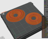
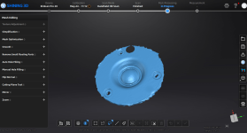
One is oval. The other is perfectly round. Picture is what they look like in the software that slices the model into gcode the printer can use. They will not be orange in real life.
One is oval. The other is perfectly round. Picture is what they look like in the software that slices the model into gcode the printer can use. They will not be orange in real life.
Attachments
I honestly have no idea what they are. I think it's a mix of wavwguide/diffraction.
The circular one is more tame. The oval one is quite aggressive. Will be interesting to what it does. If it does anything at all
The circular one is more tame. The oval one is quite aggressive. Will be interesting to what it does. If it does anything at all
I made the "low tech" version out of MDF with CNC routed waveguide, the rest is done by hand ...this
There are preliminary measurements, but publication will have to wait for a completed speaker - but I can confirm the "octagonal" bevels improve the tweeter response at all angles very much.

This looks better, but I would suggest that you try and extend the waveguide on the tweeter from where the round over starts. Making a second waveguide some distance from the first waveguide will introduce more negative diffraction than it will solve. A smooth extension of the existing waveguide into a larger termination will have a beneficial effect if done correctly.Well this took forever.... gonna test it.
Fluid,
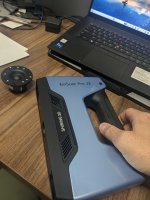
Welp.... out comes the $5,000 3d scanner then....
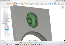
I'll scan the tweeter and try to continue the built in waveguide
Welp.... out comes the $5,000 3d scanner then....
I'll scan the tweeter and try to continue the built in waveguide
You can do it that way if it is easier but I imagine it is a simple radius that you could approximate with a ruler or calipers and make a test piece to fit in. It doesn't have to be a perfect match but ideally you would gradually transition from the existing waveguide profile, (which looks fairly conical in the pictures, maybe not in person) in a nice smooth way to the eventual round over on the cabinet edge.
From a printability perspective you probably want to make it in two pieces, one to fit the existing gap and match to the main add on piece which will be better printed flat.
From a printability perspective you probably want to make it in two pieces, one to fit the existing gap and match to the main add on piece which will be better printed flat.
The way I see it, I either leave that waveguide alone and start my new one further out or I spend the time to get that transition perfect.
I'm no expert but I imagine incorrectly transitioning a waveguide is going to have a lot of nasty effects on the response
I'm no expert but I imagine incorrectly transitioning a waveguide is going to have a lot of nasty effects on the response
You have that backwards, Trying to start another guide further out will create more destructive diffraction at a higher frequency, due to the shorter distance than leaving it alone.
The transition does not have to be perfect, the main waveguide sets the bulk of the pattern, all you need to do is smooth out the termination. A little bit of blue tack or putty will work to fill any gap for testing if it is needed.
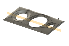
The other option is to do what you have done with the woofer and mount the tweeter in the extra baffle plate and make the transition from the edge of the face plate into a smooth edge shape as close as possible.
You want to minimize the curvature change as much as possible to minimise diffraction. Once the sound has diffracted from the waveguide mouth to a flat surface such as the faceplate or baffle putting anything else in it's path narrowing the pattern will create a secondary source that will interfere.
The transition does not have to be perfect, the main waveguide sets the bulk of the pattern, all you need to do is smooth out the termination. A little bit of blue tack or putty will work to fill any gap for testing if it is needed.
The other option is to do what you have done with the woofer and mount the tweeter in the extra baffle plate and make the transition from the edge of the face plate into a smooth edge shape as close as possible.
You want to minimize the curvature change as much as possible to minimise diffraction. Once the sound has diffracted from the waveguide mouth to a flat surface such as the faceplate or baffle putting anything else in it's path narrowing the pattern will create a secondary source that will interfere.
Yeah I have considered that, the mounting the drivers in the extra baffle. The port cannot move. I glued the inner flare inside the baffle when I built the box. I also glued the outer flare to the baffle.
I will have design the baffle so I can screw it into the plate. Maybe fill the holes with bondo.
Plan plan is to wrap the front and sides in alcantara. I'm hoping I can tuck that under the drivers to get a finished look. Cant tuck it under the port though....
I will have design the baffle so I can screw it into the plate. Maybe fill the holes with bondo.
Plan plan is to wrap the front and sides in alcantara. I'm hoping I can tuck that under the drivers to get a finished look. Cant tuck it under the port though....
That is quite an interesting thread. A bit complicated maybe. I'm very interested in measured results.
The good thing about the whole theme is, if you are into building real speaker cabinets with "normal" tools and equipment, a reasonable 25-35° edge on both sides of the baffle will get you 95% of a perfect result. Not so surprisingly, a compareable rounded shape is just as good as a simple cut. Both can be realized with basic tools. These options are not only simple to do DIYS, they will lead to an accepable look, too.
The good thing about the whole theme is, if you are into building real speaker cabinets with "normal" tools and equipment, a reasonable 25-35° edge on both sides of the baffle will get you 95% of a perfect result. Not so surprisingly, a compareable rounded shape is just as good as a simple cut. Both can be realized with basic tools. These options are not only simple to do DIYS, they will lead to an accepable look, too.
Well it started with me building a super boring 2 way which, of course, I then had to make incredibly complicated to keep it fun. And now here we are, 139 posts later
@Arthur Jackson Using a bit like that freehand is quite gutsy. You'd obviously need to go at it in several steps to make it turn out clean.
@Bmsluite You would have likely gained more from offset driver placement than the radius by itself. No doubt the radius would help some on its own, but a golden ratio driver offset would have a noticeable positive impact on the midrange linearity.
I've used wider baffles with good ÷. That mimics sideways speaker placement on a monitor desk. The larger wiggles you get with your typical 6 - 7" 2 way monitor can be minimized a little by running the tweeter HP up higher so the woofer has more directivity in that range. It may be worse with power response, but it improved off axis linearity based on my previous findings working with smaller PMC clones I built using the SS D2905-9700 + 18W8542-00 (not the newer -10 which IMO sounds worse). I tried moving around the xover by a wide range and settled on about 3k LR2.
- Home
- Loudspeakers
- Multi-Way
- Edge Diffraction Testing - Shapes