Sorry, I don't quite get it.
In the AN 39w/8ohm simulation the numbers do come out:
I=V/R= 0.375/0.22= 1.70A

In the AN 39w/8ohm simulation the numbers do come out:
I=V/R= 0.375/0.22= 1.70A
I don't think so, Karucho. Reconsider the original simulation schem here:

If you measure off the 0.65V across the emitter to base of Q4, you have to ADD the 0.1V across R17, and so the voltage from top of R15 (at the emitter of Q4) to the bottom of R16 (right side of R17) would add to that 0.65V giving you 0.75V, as predicted.
It is not easy to assess; use this above schematic, it's much easier to understand. I did not draw up the other schematic; it was done by the original prototyper, XRK971, so we should ask his thoughts.
X, what do you think?
Ciao,
Hugh
Thank you again Mr. Hugh, I just did the measurements:
VBE= 0.62v (Q4)
Voltage R17=0.34v Between R15-R16= 0.68v
It seems that the measurements vary.
Best regards
VBE= 0.62v (Q4)
Voltage R17=0.34v Between R15-R16= 0.68v
It seems that the measurements vary.
Best regards

Karucho I think its time to listen to it instead of measuring 🙂
Right Mr. Hugh, in the original simulation circuit Q4 is a 2N5401C.
I will try the other channel and as Adason comments, ready for the final test.
Regards
I will try the other channel and as Adason comments, ready for the final test.
Regards
It will work but this role requires a slower transistor (50MHz vs. 300MHz) makes it easier to keep the variable current source stable.
HD
HD
Understood, thank you for your assistance. I will leave the BD140 which I already have installed.
Regards
Regards
The variable current source is effectively a two transistor current supply, with any current variation in the upper resistor reflected in conjugate to the lower resistor such that the sums of the sense resistor voltages sum to 0.75V during the linear operation cycle. The upper nmos sets the voltage presented to the load throughout the entire waveform, giving this amplifier a single ended topology from the POV of the signal. While the pmos simply follows orders from the nmos, it ensuring a passing current keep the pmos on with no influence on the nmos voltage. So the speed in this block is not too necessary sonically - that is dominated entirely by the nmos - but the BD140 and the pmos should be reasonably matched. I have noticed that if the master bipolar Q4, the BD140, is too faster, its collector voltage (and therefore its bias voltage presented to the gate of the pmos) swings the current through the pmos and can oscillate heavily, particularly at the higher outputs of the amp. This impacts on the sound quality, and must be avoided, so R18/C12 are a Zobel, a snubber, which squashes this oscillation at the collector/base junction of Q4. Any oscillation is removed entirely if Q4 is a BD140, as these devices use a high current dies, up to 1.5A, and so the capacitances inside the transistor are high. I cannot find all the speed information on this device, but I'm pretty sure it's around 50MHz.
HD
HD
Last edited:
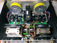
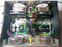
I have two types of transformers 2Χ18V 300VΑ and 2X19V 400 VA and my bias at 2.6A With the first one I get a voltage range of about 19V and 20.50V which heats up a bit and at active fan heatsinks about 43-45 C ,and more quiet and with the second a voltage range in volts of about 20.50V to 22V and at active fan heatsinks about 45_47 C with more fan noise and no heat up ....What would you suggest?
Attachments
I have two types of transformers 2Χ18V 300VΑ and 2X19V 400 VA and my bias at 2.6A With the first one I get a voltage range of about 19V and 20.50V which heats up a bit and at active fan heatsinks about 43-45 C ,and more quiet and with the second a voltage range in volts of about 20.50V to 22V and at active fan heatsinks about 45_47 C with more fan noise and no heat up ....What would you suggest?
Interesting dilemma, Nikos. 🙂
I took the lid of one of my AN4Rs, to compare my numbers with yours. I use 2x18v 300VA traffos (giving DC rails of +/-21v).
My traffos are slightly warm (after an hour of playing music) - and the temperature on the external heatsink bodies (ie. shining my gun on the metal between the fins) is 60 C on both heatsinks.
So I would say ... use the 300VA traffos - so you get the quieter option.
Because you use LT4320... and lower bias 2.2A.I use 2x18v 300VA traffos (giving DC rails of +/-21v).
Ohhhh!!! too hoooot, about 70 C and more on mosfet body.and the temperature on the external heatsink bodies (ie. shining my gun on the metal between the fins) is 60 C on both heatsinks.
i think i use the 400VA trafo 20.50-22V I think i listening more Incompressible bass with him...So I would say ... use the 300VA traffos - so you get the quieter option.
thanks Andy for your opinion.
Last edited:
Hi Mr HughNikos,
I concur with Andy, he is on the money in my opinion!
Congratulations for fine Alpha Nirvanas....
Hugh
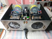
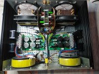
does the phenomenon that the transformer heats up during operation not concern you at all? remember that my current is at 2.6 A /4R and not at 1.7A/8R . Today I'm going to audition with the 400VA transformers... something I didn't like yesterday with the 300VA transformers.
Attachments
Hi Nikos,
If your amp uses 2.6A with 20V rails, the dissipation is 104W, ignoring the small dissipation of the early stages.
If your transformer is supplying 104W from a 300VA rating, it is about 35% loaded and this should be more than sufficient for the role.
Most transformers are designed to a winding temperature rise, and modern enamel insulation is fine up to about 80C.
I would not be concerned, lie back in your most comfortable chair and enjoy the music!!
Cheers,
HD
If it’s more than just handwarm, have you checked for oscillation?transformer heats up during operation
- Home
- Amplifiers
- Solid State
- Alpha Nirvana 39w 8ohm Class A Amp