Fine ...now it is working
changed the symbol file with text editor to the correct folder. copy it. paste it everywhere...😆
the BC550_C Bob Cordell Transistor i changed to BC557C and BC547C for now..
some errors but i can play with it...1,3V input seams the max of this amp.
thank you guys!
chris

changed the symbol file with text editor to the correct folder. copy it. paste it everywhere...😆
the BC550_C Bob Cordell Transistor i changed to BC557C and BC547C for now..
some errors but i can play with it...1,3V input seams the max of this amp.
thank you guys!
chris
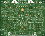
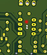
I have measured out the resistors 15 K on the mofi board, easy doing, only 5x 15 k resistors on the pcb. The 22 ohm resistors i have also marked with a red point on my picture. Perhaps it would help.
I will order CDR at Ali Express. Until the CRD 352 i will change the resistors to lower values.
Peter
hi peter
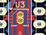
i guess you miss the change from the resistor after the opamp output from 100R to 22R.
R3 and R3A1.
kr
chris

LTspice playing arround.
1,3V input is too much..the current in R26, R28 looks saturated.
with 1,25V input it looks fine.

1,25v input

1,3V input is too much..the current in R26, R28 looks saturated.
with 1,25V input it looks fine.
1,25v input
Soldering iron warms up...
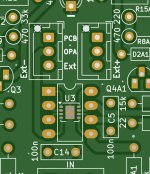
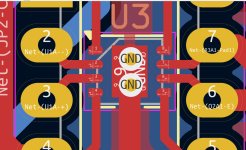
I have made an update to the pcb. Some tracks had to be changed to put an OPA footprint with thermal pad in. KiCad does not like that, two footprint in one.
But it seems to be no problem. I uploaded the gerber files to pcw way and it seems to be fine.
Peter
I have made an update to the pcb. Some tracks had to be changed to put an OPA footprint with thermal pad in. KiCad does not like that, two footprint in one.
But it seems to be no problem. I uploaded the gerber files to pcw way and it seems to be fine.
Peter
Attachments
I don't have Proteus, I don't have Kidcad or LTspice, if someone has to see it in Proteus I would appreciate it, greetings.
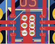
Peter its normal when including a thermal pad to make four ( say ) vias linking the pad to as large a copper area on the back side of the board as possible. You can then solder to the topside thermal pad from the back so that the solder wicks to the thermal pad from the bottom of the pcb. Bit convoluted but I hope that you can see what I mean. That gives you a much larger area heatsink and means that you don't need to solder the ic in place with hot air.
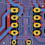
I understand, but the vias are small. On the first picture you can see the pad without vias. I had made the vias bigger. The hole has a diameter of 0,6 mm now. The normal vias hole is 0,3 mm. I can set 6 vias or two bigger ones.
Attachments

I am afraid i have sadly news....
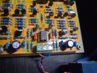
My (Mark Levison) JC2 Clone is sounding better as the C3850 Clone with mods. I have changed the preamp and with the same pieces of music i have heard both. (the Apex P30ZF is working now )
The C3850 has more bass, lower trebel. Der JC2 is more balanced. particularly noticeable by a piece of music from Mick Kolassa, called "Nothing to loose".
Without any mods, it has a better sound. I only can hope that a different OPA will help...
My Apex 30ZF is sounding better too...but more expensive.
The Amp was the same, my Goldmund Clone...
Peter
Attachments
Last edited:
Peter, I think two big holes would be better as you could get a fine soldering iron tip further into it than the smaller ones. Also the solder in the larger holes will have more thermal mass for transferring solder to the pad on the ic. If anyone tries this with an OPA2828 be sure to put flux on the ic and pcb pads and a tiny dot of solder paste on the pcb pad. Then solder the ic pins in place and turn the board over and put plenty of solder on the vias and keep the iron in place until you are as sure as you can be that the ic thermal pad has soldered to the pc.
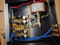
The pcb looks fine Peter. Not surprised that the JC-2 sounds different, its running the output stage at high current class A, high enough to need a large heatsink. Your JC-2 looks like the version with BD139/140 bjts on the output. There is another version which uses mosfets on the output which reportedly sounds warmer. I'm sure the C3850 withTO126 output devices running at a current high enough to need a heatsink will sound different again.
Hi PeterI am afraid i have sadly news....
My (Mark Levison) JC2 Clone is sounding better as the C3850 Clone with mods. I have changed the preamp and with the same pieces of music i have heard both. (the Apex P30ZF is working now )
The C3850 has more bass, lower trebel. Der JC2 is more balanced. particularly noticeable by a piece of music from Mick Kolassa, called "Nothing to loose".
Without any mods, it has a better sound. I only can hope that a different OPA will help...
My Apex 30ZF is sounding better too...but more expensive.
The Amp was the same, my Goldmund Clone...
Peter
thanks for your help and creating like a robot so fast the PCb and gerbers. (dont forget to change the output of the opamap 100--> 22R)
for tuning..i am not ready to build but soon.
proposal
- regulator i have not the normal 1,5A regulator i use the smaller one max 500mA- according to the datasheet i have less noise.
maybe a regulator with just 100mA will be sufficient. - solder a small film caps (100nF-220nF) under the 1000µF cap before the regulator
- solder a small film caps (100nF-220nF) under the 100µF after the regulator
- use film caps instead of ceramics in signal path
- try the normal NE5532 or with SOIC adapter the AD8599 or OPA828.
The pcb looks fine Peter. Not surprised that the JC-2 sounds different, its running the output stage at high current class A, high enough to need a large heatsink. Your JC-2 looks like the version with BD139/140 bjts on the output. There is another version which uses mosfets on the output which reportedly sounds warmer. I'm sure the C3850 withTO126 output devices running at a current high enough to need a heatsink will sound different again.
yes
i know that update from my brother with his Wayne line stage 2018 pre amplifier- he did the hot roded wayne (To-126 BJT) and he told me it is unbelievable good!
chris
Last edited:
sounds better, but has a high distortion before 20khz, so I dismissed it, although the measurements do not sound, dictate the ears.
- Home
- Amplifiers
- Solid State
- Clon C-3850