If you want the yellow PCB with PSU on-board, I could buy it for you. It will take a few weeks though.
The cost is $11 plus shipping.
The cost is $11 plus shipping.

I have performed measurements across 10/1 voltage divider consisting of 10K and 1K resistors. So: yes, load was 10K. I could have done that with, for example 1K/100R. The result would have been the same, I guess. This preamp is clean with transistors from the kit and poper selection of paris I have mentioned previously in this thread.Berlusconi did you do your distortion measurements with the C-3850 unloaded or with a load resistor? If no load I would be interested to see the results for 10k and 1k loads
EDIT: Next week I will repeat measurements with different loads.
Last edited:
... or by addng driver/output stage one could make a good standalone power amplifier. Good idea. 👍As well as a preamp the same pcb could then be configured as a headphone amp or small power amp.
Using the unregulated supply (pre 7815/7915 regulators) and then using resistors zener diodes for the op amp supply? So you don't have the dropout voltage of the regulators, which are not needed since the PSRR of the op amps is very high.However if you separated the opamp power from the rest of the circuit, using resistors zener diodes, you could use higher supply voltages which will give you more headroom and dynamic range. As well as a preamp the same pcb could then be configured as a headphone amp or small power amp. The engineer in me can't resist tinkering so if you're happy with the preamp as it is you can cheerfully ignore all of my musings, but if anyone is interested I can expand on any of the ideas.
i guess chalky means that for the opamp the max supply is 15 v rail and therefore enough. for the other stages it would be possible to have more voltage if you split the the supply on the pcb.
Are you saying it would be better to just bypass the first buffer+vas stage entirely, and then optimize the output buffer by increasing current?In a way the first diamond buffer+vas in the C-3850 gets you very little except a little more open loop gain.
The 5532 is rated for +22/-22 volt supply.
I am puzzled. Why do we need all the complication between the opamp and the output node? Can we just tie the opamp output pin directly to the feedback take-up node at the output, and delete everything in between? Is am opamp alone not good for a preamp? What do the two diamond buffers with a gain stage sandwiched in between do to help the opamp? If the good old school opamp alone isn't good enough, such as NE5532, how about modern opamps alone like OPA1656? Is there a simulation that we can find ? Thanks!
If you just use the c3580 for its intended purpose then I think that the first diamond stage is unnecessary. In that case the second stage the output diamond would usually provide a current boost for the opamp. However if you want to drive the output voltage beyond the capability of the opamp then the first diamond stage+vas transistor provides a neat way to get the extra voltage swing; provided that the opamp is powered from the main (higher) supply voltage via zeners or regulators. In broad terms I would say for a low current output preamp an opamp alone is sufficient; if you want to drive long cables or low impedance headphones then you need the opamp plus diamond buffer; if you want to maximise dynamic range or have a neat little power amp then you need an opamp+vas+output diamond ( where the vas is a diamond + vas transistor). Bryston run their input stage at +/-33V for this very reason. I guess what I'm trying to say is that the existing circuit, with a few small modifications, could fulfill all of the aforementioned applications with a single pcb and slightly different sets of parts. If someone is going to the trouble of making a pcb then wouldn't it make sense if it was as flexible as possible ( value for money and effort )?
NO! The maximum ratings are 22V each rail. that is not for operating!--> see datasheet chapter 7.1.Are you saying it would be better to just bypass the first buffer+vas stage entirely, and then optimize the output buffer by increasing current?
The 5532 is rated for +22/-22 volt supply.
recommended condition chapter 7.3 is 15Volt each rail.
why using the transistors afterwards?:
here is the answer --chapter 7.5.
maximum swing is with 15 V rail - 24Vpp - 26Vpp, so you loose on every rail 2Volts internal in the opamp (chapter 7.5 Vopp)
the opamp can maximum do 10V output swing to a bandwidth of 140kHz - (chapter 7.5 .B_OM)
therefore it makes sense that the stages after the opamp are existing 😉
chris
Attachments
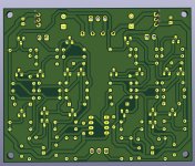
I made a PCB, you can have a first look. Perhaps some components have to move, i will see. I updated the schematic with other values.
R1/R1A1, Q1/Q1A1 and so on. Capacitors and diodes have the old values. NE5532 is rotated !!!
The groundtracks are no more necessary, only for my use in the moment. The pcb has a groundplane.
If someone has an idea to make someting better please tell me...
Greets
Peter
R1/R1A1, Q1/Q1A1 and so on. Capacitors and diodes have the old values. NE5532 is rotated !!!
The groundtracks are no more necessary, only for my use in the moment. The pcb has a groundplane.
If someone has an idea to make someting better please tell me...
Greets
Peter
Attachments

Last edited:
Hey, I bought one of these a little while back and just got to my first listen today, I'm pretty pleased. I've been running passive preamp or just volume control from the source for a while, but sometimes find myself gain limited, so I wanted an active unit. So far, so good, but I don't have another active preamp to compare directly. I've got the kit that has 3 input relays, and the board says V1.4.
I may roll opamps to see what happens, though in the past I haven't felt like I accomplished much by doing so.
The Beeny suggestions about changing gain resistor and (C7 and) C8 - I think they were just aimed at increasing bandwidth, do I have that right? He goes to pretty extreme ends there, I don't think I need to chase 100+ kHz, but maybe I've got it wrong and they have some impact in the audio band?
Also, I think he says look for a 50k or even 25k volume pot. Why? 100k is what I had laying around.
The kit loadout has Wimas for the 100pf caps, but it's still a ceramic for the 10pf (like the mofi yellow board), I'm not sure if I care.
Thanks for the effort being put into this kit, I'm watching to see what happens!
Hello,
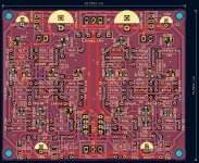
i have controlled the pcb and found one too small track...thats all.... corrected. DRC with two mistakes, because i changed the output connectors (i know, i have done 🙂 ).
One ground via, 15 K resistor and one led are new on the pcb. Diode bridge i changed to a smaller one. The feedback tracks now in 1,5 mm.
I can give no guarantee, but i think the pcb with its components will work. The pcb size is similar to the pcb from "Mofi".
The Metz Connect AKL connectors 3,5 mm will fit too https://www.reichelt.de/wannensteck...-p36644.html?&nbc=1&trstct=lsbght_sldr::36629
Greets
Peter
Attachments

Last edited:
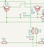
very nice pcb. Do you think you can do some TP-Test points?
e.g.
after output opamp, after the R12(33k) to check DC there.
Base of BJT Q7/Q8
chris
e.g.
after output opamp, after the R12(33k) to check DC there.
Base of BJT Q7/Q8
chris
Last edited:
perfect...like this...yes...
maybe others have some ideas....so wait....you are fast
BTW:
whats about your idea to build the DX blameless ST?
maybe others have some ideas....so wait....you are fast
BTW:
whats about your idea to build the DX blameless ST?
Last edited:
In this way ? Q7/Q8 base (are together), 33k to the output R21/R22/R26...or after R26 ? You can have a testpoint after 33k and to the output after R26
Three testpoints marked
My Blame ST is running fine. I have built the Blame MKII Supercharged too... not testet the MKII, but already in a case on the heatsinks...
https://www.diyaudio.com/community/threads/blame-es-st-reloaded.410850/
I have made pcb' s for the old Mini Crescendo (Elektor1984, the original Mini Crescendo is running) , NAP250, NCC200, Baby Lynx, FH9 XRK Mod.....and and...😉
Attachments

Last edited:
- Home
- Amplifiers
- Solid State
- Clon C-3850