Please use NTC’s instead of plain resistors for the soft start. As I found out the hard way, if your relay ever fails to switch on after a few seconds, the high current will burn the resistors into a flaming mess.Soft start for a switch with led 24V and a simple DC Blocker ... .
I use two 8D-40 in series and that provides 16ohms series initial resistance. If the relay fails to bypass, it becomes 1ohm and gets hot but not flaming hot.
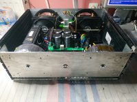
Wonderful build by the way. I love your double stacking the boards to keep a compact form factor. A lot smaller than my A40 design which is going to production this week. You can see the two NTCs on the soft start in the central board which provides a solid state relay for the soft start and the speaker output DC protection.

Very nice..Please use NTC’s instead of plain resistors for the soft start. As I found out the hard way, if your relay ever fails to switch on after a few seconds, the high current will burn the resistors into a flaming mess.
I use two 8D-40 in series and that provides 16ohms series initial resistance. If the relay fails to bypass, it becomes 1ohm and gets hot but not flaming hot.
Wonderful build by the way. I love your double stacking the boards to keep a compact form factor. A lot smaller than my A40 design which is going to production this week. You can see the two NTCs on the soft start in the central board which provides a solid state relay for the soft start and the speaker output DC protection.
View attachment 1338606
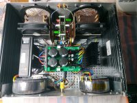
Is that big red cap (Wima?) a coupling capacitor of is this a DC-coupled amp?
That’s a 10uF Wima MKP coupling cap on the audio input. Output is DC coupled of course. The input cap helps to prevent issues with customers’ sources having DC offset which would make speakers have DC and this would trip the protection SSR.
This amp has a dual rail CRC PSU on the amp board. No cap multiplier here. The rectifiers are bolted to the heatsinks to dissipate the Class A currents through them. Two per amp board.Looks like you've got rectifier/filter for each rail on each amp board. I've not seen that before. Cool!
Hello Hugh,
Please see:
1. image of LT4320's
2. Left side SLB w/V's
3. Right side SLB w/some V's. This is the problem one to be fixed after the Left SLB.
I hope this shed's some light on my problems.


Please see:
1. image of LT4320's
2. Left side SLB w/V's
3. Right side SLB w/some V's. This is the problem one to be fixed after the Left SLB.
I hope this shed's some light on my problems.
What are the additional wires for in the faston crimps on the AC side?
Is that the same side of the power supply your having problems with?
Is that the same side of the power supply your having problems with?
Hi Vunce,
Those are the 2 wires from the secondaries for the low cap psu to be used with the speaker protection module's. I have them on both sides as this is a dual mono build, they are not hooked up, hence the blue tape on the ends.
Those are the 2 wires from the secondaries for the low cap psu to be used with the speaker protection module's. I have them on both sides as this is a dual mono build, they are not hooked up, hence the blue tape on the ends.
Last edited:
Myles,
Thanks for the schematics!
You have 2.2V across the large pass transistors for both regs so it looks OK.
If you see 0.6V across BE on Q9 and Q11 then the regs are working correctly.
So if voltage is not reaching the amp modules then it can only be a wire missing or broken so check for mistakes there.
If D1 and/or D2 are not lighting up check the polarity of the led is correct because the voltage tells us they should light. I am concerned about 31.5V and 31.2V at the ground and makes me suspect the link wire from C15/R14/C17 to ground is missing.
Hugh
@xrk971Please use NTC’s instead of plain resistors for the soft start. As I found out the hard way, if your relay ever fails to switch on after a few seconds, the high current will burn the resistors into a flaming mess.
I use two 8D-40 in series and that provides 16ohms series initial resistance. If the relay fails to bypass, it becomes 1ohm and gets hot but not flaming hot.
Wonderful build by the way. I love your double stacking the boards to keep a compact form factor. A lot smaller than my A40 design which is going to production this week. You can see the two NTCs on the soft start in the central board which provides a solid state relay for the soft start and the speaker output DC protection.
Thanks for your kind words.
I dont finish it yet i need a front plate from wood laminate match to my other audio system. I will use those 8D-40NTC only two in series?
Did you notice any positive difference with the double CRC and classic rectifier instead LT4320 and cap multiplier?
Big tafos....how many VA are they?
Attachments


Last edited:
Hi Nikos,
The CRC PSU is quiet enough but not dead silent like the SLB. These are some of the tradeoffs we make for a commercial product. With a well designed CRC, we can get the residual 60Hz main peak to about -80dB at the speaker. Which is not bad because it means you can press your ear to the speaker cone and barely hear a buzz. With SLB it should be inaudible like you cannot tell that the amp is turned on. But that’s why we have DIY, to go all out on amps with all gadgets. I am using custom made 22v 200VA toroidal trafos.
Here is the FFT for 1kHz 10E excitation into an 8ohm load on the A40. You can see the noise floor below the mains peak at 80dB. Also, the very nice harmonic profile of this amp.
Hi Myles,
Sorry about your issues on SLB. From looking at the voltages you posted, they all look good. This means the LT4320 is not fried (because you won’t get any DC otherwise) and your BJT pass transistors are not fried since there is 3v drop.
I usually don’t use dim bulb testers on Class A amps as they draw a lot of current in quiescent mode that will make the bulbs glow even when all is normal.
An oscillating glow is a problem though.
What I do to check an amp at turn on is to connect a DVM across the source resistors at the amp output to measure the instantaneous bias current and also another DVM at the output voltage to measure offset. Look at those numbers and flip the switch and if current (using Ohms law I=V/R so for 0.15 ohm that is ) exceeds 3A about 450mV across 0.15ohm resistor, 2 seconds after turn on or DC offset at speaker out exceeds 2V, immediately throw the switch off and investigate.
Hope that helps.
Full Monotonic decrease harmonics profile .Cool...very nice.
Audible character ? SLB vs classic PSU ?
Audible character ? SLB vs classic PSU ?
Last edited:
Thanks X and Hugh,
I will investigate all you have suggested and post my results. Sunday's are the relax days (golf). So will get to this next week. Thanks for the tip abput the DBT and Class A. Since the circuits powers up OK, I can leave it out of the chain and use the Variac.
One question X: I think I know the answer but, can the source resistor current be measured anywhere else?. My BPR resistors are tight to the top of amp board, and I have nipped off the leads on the bottom of the amp board. I may have to desolder the BPR's and raise them a bit if possible or use a new set.
MM
You can also measure the current across the SLB resistors on the CRC part. Where you got the sparks! Make sure you measure in voltage setting across the KOA BPRs. I sort of remember installing test lead loops on these resistors for this reason.
Myles,
You can measure the voltage across the two source resistors by measuring from the source of the NMOS to the source of the PMOS.
Divide this voltage by the total resistance of the two resistors to get close to the quiescent current of the amp.
Hugh
You can measure the voltage across the two source resistors by measuring from the source of the NMOS to the source of the PMOS.
Divide this voltage by the total resistance of the two resistors to get close to the quiescent current of the amp.
Hugh
Hugh, X, Nikos, Vunce, thanks for all the help so far. I was measuring the base to emitter voltage on Q9,Q11, and they were 1.7 V not the 0.6V as Hugh mentioned. I went to reposition my self for better access and some how got a short that knocked out the PV side on the good SLB (or so I thought) and it knocked out the SFP also.
So, I have decided to redesign the layout of of the chassis for better access to components, rebuild the SLB's, and find out what happened with the SFP. I am going to begin with a fresh mind and perform test's and record V's as I go along. But first of all I am going to take a break for a few days. Not to worry, I am not giving up
Until I post again...... 😉
MM
Myles,
Kudos to you for persevering and learning through the process. 🙂
Another humble suggestion from my side - would you consider starting with a standard CRC power supply with your AN first? It will be easier for you to set up and get the amp running while you work on the SLB. And remember, most builders across the forum are building their amplifiers with CRC power supplies, and the AN will work fine with a good CRC power supply.
Hi Myles,Hugh, X, Nikos, Vunce, thanks for all the help so far. I was measuring the base to emitter voltage on Q9,Q11, and they were 1.7 V not the 0.6V as Hugh mentioned. I went to reposition my self for better access and some how got a short that knocked out the PV side on the good SLB (or so I thought) and it knocked out the SFP also.
So, I have decided to redesign the layout of of the chassis for better access to components, rebuild the SLB's, and find out what happened with the SFP. I am going to begin with a fresh mind and perform test's and record V's as I go along. But first of all I am going to take a break for a few days. Not to worry, I am not giving up
Until I post again...... 😉
MM
Sorry to hear what happened. Years ago when I was first building an amp Hugh designed (it was the Quasi, I think) - I blew out a MOSFET and the drivers when I shorted out a main power pin to some other part that it was not supposed to touch. The amp was basically toast (smoke and melted parts everywhere) and it took a lot of effort to recover. It was very disheartening. But Hugh told me this about when poking around on a live circuit: “be careful as if you were backing your shiny new car out of a garage not to scrape your paint job.” So basically, slow down and be very careful. I find it helps to cover the probes with shrink tubing only to expose the tip. This helps a lot.
Good luck on your recovery efforts. Hopefully it’s all easily replaced with a few parts.
- Home
- Amplifiers
- Solid State
- Alpha Nirvana 39w 8ohm Class A Amp