So today I hooked up the PeeCeeBee to my Vandersteen 3As. I've got my Cambridge Audio BluRay player as source, going through a home-built controller (selector switch and stepped attenuator).
I think I like this slightly better than my Honeybadger build, which is saying a lot. The first thing that jumps out at me is the incredible detail. It's mostly noticeable with percussion instruments I feel like I get a sense of the space the recording was made in. The next thing I notice is the imaging and placement of instruments - if the recording allows for it. There is a separation of sound sources which I don't think I heard with the Honeybadger, with the right recording.
But I keep having this nagging feeling like there's too much of something in the upper frequencies, that I can't quite articulate. Too much detail? There's something really "forward" about the sound. I think it may become tiring to listen to for too long. It makes my Honeybadger sound mellow and relaxed by comparison. It could be a good thing or a bad thing, depending on the recording and what I'm in the mood for.
All-in-all, I think this is an amazing amplifier! Thank you Shaan for providing us the opportunity to build it!

Finally completed the mono blocks build... mighty pleased with the final outcome.


...
...
Congratulations. I just finished mine recently also. T think you're going to find you don't need so much heatsink. My amp is just slightly warm.
Please tell me your impression of the sound after you've given them an audition.
Please tell me your impression of the sound after you've given them an audition.
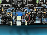
I'm using a 300W +/- 45V SMPS from Connex Electronics.
The only input is TOSLINK to a Subbu V3 DAC. That's the green board.
I think I measured 206 Watts into 4R before clipping. I don't remember what I measured into 8R.


The only input is TOSLINK to a Subbu V3 DAC. That's the green board.
I think I measured 206 Watts into 4R before clipping. I don't remember what I measured into 8R.
Question - there are ceramic caps in the BOM, 47pf, 100pf and 220pf all rated at 500V. Is that really the minimum voltage rating, because I have 200V in my stash and hoping to use those.
Follow-up questions.
1) anyone have thoughts on using 200V caps vs. the spec'd 500v?
2) Suggested +/-50V rails - what is the maximum? Asking because I have been running V4H at 65Vdc and wanted to at least try V5 in the same chassis/PSU. I only run easy 8-ohm load speakers, so won't be pushing high wattage or current
3) I have the suggested NJW0302G/0281G, but also have the higher wattage MJW1302G/3281G. Was planning to use the higher wattage ones, since I'm planning to run at +/-65Vdc (I have other higher wattage, but they are in TO-264 and would be a tight bend on the legs to make those fit)
@shaan - like you V4, love your V4H and expecting the same great sound with the V5. Also enjoy the thicker boards and extra copper - need a hotter iron, but solder flows nicely. Thanks for making this available to us DIY guys.
Couple pics of my first channel in progress
@bstang, wish I could help you with the questions. The only reference that shaan makes to any capacitors is on page 1 of this thread. Click on the GB, then under Description in the second paragraph, their is reference to some cap's. A lot is above my pay grade, but I wish you luck in your build.
I have not heard from shaan in a long while, not sure what his situation is these days.
Regards,
MM
I have not heard from shaan in a long while, not sure what his situation is these days.
Regards,
MM
I don’t see a reason why you can’t use the 200V caps looking at the schematic. As long as you have reasonably close picofarad values to the ones listed in the bom/schematic.Question - there are ceramic caps in the BOM, 47pf, 100pf and 220pf all rated at 500V. Is that really the minimum voltage rating, because I have 200V in my stash and hoping to use those.
Best,
Anand.
Well got one channel up and running and only one issue - I had 40V on the output when I powered it on for the first time. If you look closely at my pictures (can't believe I did it) but I placed Q2 in backwards. Found the issue as soon as I applied power to set the VAS current, glad I had a second DMM on the output.
Easy enough to fix, but takes a lot of heat to get all the solder out of the holes on these boards - a minor blow to my ego, thought I was going to be perfect on this one??!! (yeah right!!)
Easy to set the VAS, but the DC wanders a bit, same thing when setting the BIAS, the bias and DC tended to wonder a bit - took about 30-mins after an initial 30-mins of warm-up to get Bias set and be pretty stable +/-10mV at 145mA (or 145mV across a 1-ohm resistor on the -VEE).
Currently I'm listening to the V4H for my Right channel and the V5 for my Left channel. Biggest difference is the V5 runs cooler. Otherwise, the sound is close to V4H, with a little more detail, not as "warm" sounding in my system. But I really have to listen to pick out the differences between the two, I would be happy with either in my system.
I'll probably listen for a few more days and then start work on the 2nd channel.
Set-up: Using NJW1302G/NJW32814G for outputs, MJE15032/MJE15033 drivers, powered with +/-65Vdc rails from a 1200w SMPS and I'm using my previously mentioned 200V ceramic caps currently (have some silver-mica film caps to try as well. Everything else follows the BOM suggestions.
Attachments
Congratulations. I promise you that you are not the first person to install a transistor backwards.
Please use a smps from Micro Audio ( Cresnet ) much better .I'm using a 300W +/- 45V SMPS from Connex Electronics.
The only input is TOSLINK to a Subbu V3 DAC. That's the green board.
I think I measured 206 Watts into 4R before clipping. I don't remember what I measured into 8R.View attachment 1326176View attachment 1326177View attachment 1326178
You will notice better sound then with those from Connex .
HiSo today I hooked up the PeeCeeBee to my Vandersteen 3As. I've got my Cambridge Audio BluRay player as source, going through a home-built controller (selector switch and stepped attenuator).
I think I like this slightly better than my Honeybadger build, which is saying a lot. The first thing that jumps out at me is the incredible detail. It's mostly noticeable with percussion instruments I feel like I get a sense of the space the recording was made in. The next thing I notice is the imaging and placement of instruments - if the recording allows for it. There is a separation of sound sources which I don't think I heard with the Honeybadger, with the right recording.
But I keep having this nagging feeling like there's too much of something in the upper frequencies, that I can't quite articulate. Too much detail? There's something really "forward" about the sound. I think it may become tiring to listen to for too long. It makes my Honeybadger sound mellow and relaxed by comparison. It could be a good thing or a bad thing, depending on the recording and what I'm in the mood for.
All-in-all, I think this is an amazing amplifier! Thank you Shaan for providing us the opportunity to build it!

I don't know if we're talking about the exact same thing but this somewhat odd HF behaviour was gone after changing the two 470R resistors to 1K/2K2 (either is fine) (R19/20) and the two 220pF capacitors to 100pF (C13/14). It's basically a slight ringing due to a combination of VAS loading and the baxandall compensation network characteristics. With these changes of components, it has been tranquil around here.
I will update the schematic and BOM with these parameters. I am trying to give Q25 and 26 some space without omitting the mosfets (for easier heatsink attachment). I have tested the amp with discrete 1A rated fast diodes in their place but ended up going back to the MOSFETs' parasitic diodes. I was about to omit the two trimmers VR1 and VR2 as the VAS bias can be permanently set to a safe bias using 270R or 330R instead of the trimmers (due to the limiters), but this takes away the offset control so the idea got discarded. All component markings on the PCB remain unchanged.
Question - there are ceramic caps in the BOM, 47pf, 100pf and 220pf all rated at 500V. Is that really the minimum voltage rating, because I have 200V in my stash and hoping to use those.
Follow-up questions.
1) anyone have thoughts on using 200V caps vs. the spec'd 500v?
2) Suggested +/-50V rails - what is the maximum? Asking because I have been running V4H at 65Vdc and wanted to at least try V5 in the same chassis/PSU. I only run easy 8-ohm load speakers, so won't be pushing high wattage or current
3) I have the suggested NJW0302G/0281G, but also have the higher wattage MJW1302G/3281G. Was planning to use the higher wattage ones, since I'm planning to run at +/-65Vdc (I have other higher wattage, but they are in TO-264 and would be a tight bend on the legs to make those fit)
@shaan - like you V4, love your V4H and expecting the same great sound with the V5. Also enjoy the thicker boards and extra copper - need a hotter iron, but solder flows nicely. Thanks for making this available to us DIY guys.
Couple pics of my first channel in progress
View attachment 1328183 View attachment 1328186 View attachment 1328187
200V rated caps are probably okay, but some of them have to deal with large voltage swings at high frequencies, so a more robust model would be better for best long term safe operation.
I have successfully run the amp at 56V rails without problem into 8ohm speakers that dip close to 4ohm, but I suggest 50V max for nominal 4ohm speaker operation. This is to keep the power trannies well within their SOA upto clipping during an impedance dip at certain frequencies. As per your test, it is stable with 65V rails. I think you can feel safe with this as long as the speaker impedance don't dip too much.
Happy to know you like the previous peeceebees; looking forward to know your thoughts on the V5.
edit: To everyone, please post any of your questions that I missed. Will try my best to attend to them.
Last edited:
Thank you Shaan. Yes. I think there may be a high frequency oscillation going on. I. Couldn't find it with the O-scope so I thought it was just my imagination. I'll make the changes you recommend and report back!
@shaan I built my 2nd channel board and have been listening tin stereo the last couple days and on my test speakers everything sounds fine, but after changing to my reference speakers (more reveling in mids and highs) there is something missing in the midrange, and a scratchy harshness in the upper midrange. Test speakers have a pretty good "smile" frequency response, where my reference speakers are close to flat from 100Hz-14kHz
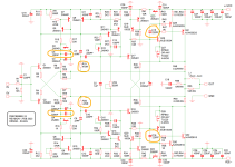
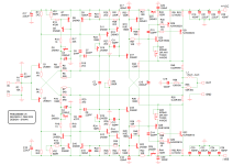
I want try your suggestions above before I make any final listening impression comments, but a little confusion on my as-built schematic (attached) and the one in Post #1 of this thread.
1) Post #1 schematic appears to have omitted C5/C6 (100nF) which alters the Capacitor numbering. When you mention C13/C14 being changed from 220pF to 100pF, would that be C15/C16 on the attached schematic? Both schematics have the same disclaimer - Revision 1 and Feb 2023?
2) Post #1 schematic has R19/R20 as 2k2, but you mention 1k and 2k2 above and previous thread post. Do you have a preference/recommendation since I have both resistors on hand.
3) Thoughts on C5/C6 being omitted in the Post 1 schematic - should those be removed from my boards as well?
Thanks,
Paul
Attachments
Hi Paul.
Schematic and BOM has been updated with the latest version in both threads.
Thanks for your report.
but a little confusion on my as-built schematic (attached) and the one in Post #1 of this thread.
Schematic and BOM has been updated with the latest version in both threads.
Thanks for your report.
Wanted to come back after making the suggested changes to C5/C16 (220pf to 100pf) and R19/R20 (470r to 1k). I'm still trying to find time to get some hours of real listening sessions in... but the upper-mid harshness is gone, replaced by a crystal clear, revealing nature to what I've heard so far.
I suggest if you have not done these changes, to do them - the sounds difference was immediately noticeable in my system.
I have also noticed this amp is very well behaved when you "beat on it", even running at +/-65Vdc (not recommended) but my speakers are a very easy load at ~7r actual. Strange to say, but it also sounds better at 70-75db, instead of my typical 50-55 (background music ) in my small office.
I will try and come back after I've had some listening time with the updated version, but so far I'm glad to have built it and not missing my V4H (yet).
Thanks @shaan for the design and your assistance
Wanted to come back after making the suggested changes to C5/C16 (220pf to 100pf) and R19/R20 (470r to 1k). I'm still trying to find time to get some hours of real listening sessions in... but the upper-mid harshness is gone, replaced by a crystal clear, revealing nature to what I've heard so far.
Welcome to PeeCeeBee V5. I hope you have many pleasant sessions with this one.
I suggest if you have not done these changes, to do them - the sounds difference was immediately noticeable in my system.
+1 ☝🏼
I have also noticed this amp is very well behaved when you "beat on it", even running at +/-65Vdc (not recommended) but my speakers are a very easy load at ~7r actual. Strange to say, but it also sounds better at 70-75db, instead of my typical 50-55 (background music ) in my small office.
I will try and come back after I've had some listening time with the updated version, but so far I'm glad to have built it and not missing my V4H (yet).
Thanks @shaan for the design and your assistance
Glad to see you resonating what I looked for in V5 when it was taking shape - not miss V4H.
Though the slight midrange swell of V4/V4H does put it in a special place for me, overall I felt V5 to be a worthy successor, with a more honest rendition of the music and without a "favourite" frequency band.
Felt very happy reading your post. Looking forward to read your impressions following further listening.
Thank you!
If anyone reading this thread is interested, PCBs are available.
https://www.diyaudio.com/community/threads/peeceebee-v5-gb.395709/page-11#post-7752145
https://www.diyaudio.com/community/threads/peeceebee-v5-gb.395709/page-11#post-7752145
- Home
- Group Buys
- PeeCeeBee V5 discussion thread