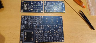
Shaan is working on the supporting documentation for V5, I’m sure he will release the info as soon as he is satisfied with it.
Hi shaan,
Just looking into parts I have, can you answer the following thanks.
For C3,C4 and C15 (2200uF) - what is the voltage rating you are using to suit a can size of 10mm DIA and 5mm lead spacing?
6.3V, 10mm dia.
C15 can be as low as 10uF without any issue, or even 10000uF. Good if it is low impedance type. This capacitor makes it possible for both Q17 and Q18 to drive both Q25 amd Q26 bases in a pure push-pull fashion i.e. makes a low impedance AC path for both the former pair's emitters and latter pair's bases. It is fine for it to have such low voltage rating because the DC voltage around this cap will be about 2.3V and kept nearly constant.
For R49 and R50 at 0.22R / 5W - what part number are you using?
For R55 and R56 at 10R / 5W - what part number are you using?
I am using ceramic body 5watt vertical mount resistors bought from local shops, these are usually low inductance types.
Also looking at the schematic and board layout - there are some discrepancies with capacitor numbering - I assume you are finalizing this as you put a BOM together.
I guess the close placement of numbers as well as the components is causing confusion. To make it easier I am doing the same as mentioned in this post, second paragraph. If you mean something else please specify.
Hi shaan,
Thanks for the answers on the electro caps and the 5W resistors - all good.
As for the comment on some differences, in going through the schematic and pcb layout shown in your 1st post to see what components I would need to buy, I found the following:
1. Film cap next to R9 on pcb silk screen is not labelled.
2. Film cap next to R10 on pcb silk screen is not labelled.
3. The 2 electro caps labelled as both being C1 at each end of the pcb, I assume are what the schematic shows as C17 and C18 - however C17 and C18 are labelled on the silk screen and on the schematic as 100nF film caps already. So these 2 electro caps will need to be corrected with their numbers oin both the silk screen and the schematic.
4. Just a comment - R39 and R40 as they appear on the silk screen seem to sit slightly 'under' transistors Q19 and Q20.
No problems at all shaan, I am going to double check my parts today and I will let you know if I see anything else out of the ordinary.
A few more comments after another check shaan.
The unlabelled film caps I referred to in my post above, next to resistors R9 and R10 on the pcb are not on the schematic - so they are either redundant or missing off the schematic with appropriate numbers to be added.
Maybe, to make the silk screening just a bit more uncluttered, you could remove the capacitor symbol in the rectangular silk screen box for the film/ceramic caps and insert the cap number in the box - like you have done for the resistors.
While I am asking questions, for L1, what was the enameled copper wire size, number of turns and former size, thanks?
Everything else seems to crosscheck fine with the schematic and pcb layout silk screen.
I just finished adding those to the schematic, along with correcting all the previously pointed errors. Except R39/R40; they are supposed to sit close to the bottom of the transistor.A few more comments after another check shaan.
The unlabelled film caps I referred to in my post above, next to resistors R9 and R10 on the pcb are not on the schematic - so they are either redundant or missing off the schematic with appropriate numbers to be added.
Just finished doing that as well.Maybe, to make the silk screening just a bit more uncluttered, you could remove the capacitor symbol in the rectangular silk screen box for the film/ceramic caps and insert the cap number in the box - like you have done for the resistors.
Will finish the rest including the BJT markings tomorrow. It's already 5 in the morning here. Thankfully someone else is sound asleep.
1-1.5mm, 18-21 overlapped turns (3x6 or 3x7), 10mm former.While I am asking questions, for L1, what was the enameled copper wire size, number of turns and former size, thanks?
Thanks again shaan, I assume you will update the revised schematic and pcb layout in the 1st post of the GB thread.
Hi Shaan, great to hear your design developed so much. I have build the first version with 2 MOSFET per channel with a small upgrade that you proposed that time. If I would like to ask you how your latest design would compare with the first one sound wise? I am not interested in power, only sound accuracy and timbre. Thanks
Last edited:
Hi Adrian.
V5 does indeed sound more accurate than V4/V4H, including much more retained clarity and timbre in both low and high power outputs. You can safely run the amp from 35V rails and with single pair power BJTs, like the V4. During its development I was very much keen to make it sound at least as appealing as the V4/H if not better; adding zeroes to the THD number was less of a priority (there are so many amps with so many zeroes already!). If you liked V4's sonics, then I believe you will love V5's. 🙂
V5 does indeed sound more accurate than V4/V4H, including much more retained clarity and timbre in both low and high power outputs. You can safely run the amp from 35V rails and with single pair power BJTs, like the V4. During its development I was very much keen to make it sound at least as appealing as the V4/H if not better; adding zeroes to the THD number was less of a priority (there are so many amps with so many zeroes already!). If you liked V4's sonics, then I believe you will love V5's. 🙂
@shaan
Since I am somewhat unfamiliar with this input stage (which shares tidbits with the V4H v2), what is your advice for those of us who have balanced/differential sources?
Use a transformer? Use a modified instrumentation amplifier using opamps, i.e. AMB alpha 24 or XRK’s BTSB or another variant like the THAT1200 chip?
Anything simpler? Or would that require hacking the pcb?
Best,
Anand.
How much is the damping factor ?
Will test and share shortly.
@shaan
Since I am somewhat unfamiliar with this input stage (which shares tidbits with the V4H v2), what is your advice for those of us who have balanced/differential sources?
Use a transformer? Use a modified instrumentation amplifier using opamps, i.e. AMB alpha 24 or XRK’s BTSB or another variant like the THAT1200 chip?
Anything simpler? Or would that require hacking the pcb?
Best,
Anand
Use the positive output and ground. With 29dB gain the amp can put out full power with 1.2VRMS. But if noise is an issue with that config then a transformer will be excellent.
Hi Shaan,
I have four pairs MJW21195/6 and two pairs 2SC3856/2SA1492
Is any of them suitable? If yes, what power do you estimate to get out of the latest? One pair per channel
Both at +-48Vdc
I have four pairs MJW21195/6 and two pairs 2SC3856/2SA1492
Is any of them suitable? If yes, what power do you estimate to get out of the latest? One pair per channel
Both at +-48Vdc
I also looked at shaan's PSUs, but in the end I chose the one from Astx, ...(in black)
My black edition Softstart + SSR3, PSU is in production...
I'm just waiting for pcb V4H & V5

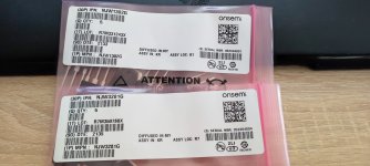
So I've looked through my home stock, I have the following pairs available for the V5:
My black edition Softstart + SSR3, PSU is in production...
I'm just waiting for pcb V4H & V5

So I've looked through my home stock, I have the following pairs available for the V5:
- 2SC5200OTU/2SA1943OTU
- NJW0281G/NJW0302G
- NJW3281G/NJW1302G
- MJL4281AG/MJL4302AG
- Home
- Group Buys
- PeeCeeBee V5 discussion thread
