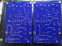
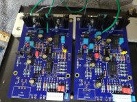
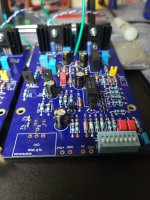
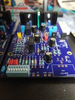
All the info is in both, but the page show above is unique to the other document and I like the chart format.
I made some progress populating boards. I presume no resistor is needed for the LEDs wired off the boards.
I got stuck when I realized the back plate hole for the "output" DC doesn't fit the Neutrick D XLR. Before I muck this all up, os there an ideal method to increase the hole diameter to fit the Neutrick D XLR?


I got stuck when I realized the back plate hole for the "output" DC doesn't fit the Neutrick D XLR. Before I muck this all up, os there an ideal method to increase the hole diameter to fit the Neutrick D XLR?
Why not use the “cable gland” as outlined in the build doc?
Otherwise your going to need a stepped drill bit.
Otherwise your going to need a stepped drill bit.
The only reason is I already have two XLRs (male & female) and a cable that interconnects. If someone can point me to the cable with open end and the "gland" to use, I suppose I can do that and avoid drilling. I didn't realize the back plate holes were different when I ordered the parts I thought I needed. Stepped drill makes sense and I'm just no super confident having never drilled from this large hole to an even larger hole before. I fear I'll screw it up somehow and was looking for advise from others who have already accomplished the task.
Thank you @rhthatcher !!!! BTW, you're PSU kit is perfect! Thanks for making that so easy for us!
The Pearl 3 is for me ma 😉
Thank you @rhthatcher !!!! BTW, you're PSU kit is perfect! Thanks for making that so easy for us!
The Pearl 3 is for me ma 😉
if memory serves the gland is specified in the BOM and the "open ended" cable is easy... just cut off the (right) connector. voila!
The good news is you don’t need the gland to hook it up and test and/or use. It’s just nice to have in case you get klutzy and pull on things too hard. So you can do everytihng, and add the gland when it arrives.
I think I'm more of a "driller" than a "cable cutter" so I shall report back. I'm also considering replacing the front of the PSU chassis switch with a push button, so I just need to gather up the strength and tools to make it work.
I just got one from BOM, perfect fit. I've also used the stepped drill bits, but I would just order the part.if memory serves the gland is specified in the BOM and the "open ended" cable is easy... just cut off the (right) connector. voila!
Listened to the 49720 in DIP package yesterday, and it sounded good to these ears 👍.I will, when it´s finished. For now as attempted first try, I installed LME-49720 metal can. Will see, how this plays out 😉
After a bizzillion album sides, the "haze" I mentioned at first has burned off. Hard to tell what is what as I changed cartridges as well. Some could have been misalignment, suspension breaking back in, etc. Very clear and punchy, lots of gain. Really want to try the other new MC, but I've got this one sounding so good I dont want to change it! Plus, I dont need any other variables until all settles out. so far, so good. dead quiet as well.
Russellc
Russellc
Why C16 (100pF) matters: I was scratching my head wondering why some folks were hearing "strange stuff" when using MM cartridges (i.e. when J2 shorts the R9 and R22) so I broke the feedback loop in the first gain stage with a 22R resistor and hooked up the network analyzer:

Why C16 (100pF) matters: I was scratching my head wondering why some folks were hearing "strange stuff" when using MM cartridges (i.e. when J2 shorts the R9 and R22) so I broke the feedback loop in the first gain stage with a 22R resistor and hooked up the network analyzer:
So what did you and Bode find?
The online build guide shows the gnd from the 2 boards going directly to the gnd lug on back panel. Is there a consistent experience as to which is better the former or running to the chassis gnd on the bottom panel and then to the gnd lug?
- Home
- Amplifiers
- Pass Labs
- Pearl 3 Burning Amp 2023


