You need a wide bandwidth transformer to place the VNA in the feedback loop.Just asking, will try the above method but leave slack to experiment if need be.
Apologies in advance it I missed it in guide documents, but I never saw the XLR on the end of the umbilical addressed regarding shield, pin 1 and tab.
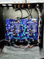
It made sense to me to treat it such that it connected all the way through. To that end, I connected pin 1 to tab 1, just like on the chassis mount XLR jack. The shield is also connected to pin #1. The other end of shield is grounded to chassis on corner of PS pcb, which then goes to chassis. I wasn't sure as I have seen interconnect shields floating on one or both ends. I figured it would be easy to cut any that were unneeded.
It is very quiet. Even with head phones, I thought it was dead until needle dropped!
Russellc
I assumed they did it via metal leg of PCB and scratched the coating. I made a chassis ground bolt.That being said that guide doesn't even show a bottom panel gnd.
I have gotten into this habit with phono pres. My preferred back panel ground has two plastic pieces that like those with chassis mount RCA jacks isolate it from the back panel.I took mine to chassis ground, also ran wire from back panel ground post to chassis ground. Complete silence.
A short thick wire goes to a bolt in floor for chassis ground point. This part would not fit between the two jacks, so I went with the BOM part, but the wire was in place already ...
That is what I did, plus a lot of additional scratching to get all of the panels grounded. IIRC all four leg positions on PCB are tied to ground.I assumed they did it via metal leg of PCB and scratched the coating. I made a chassis ground bolt.
Instead of a jumper connecting all to ground?PCB ground to the post, not the chassis floor.
The post is ground. Put everything there to begin, only make it seperate if you have problems.
I was incorrect in post #3467, after taking a look I see it is only grounded through the post and the ground on the power supply cable.
BTW, switching this thing on make sure preamp is on mute 🔕. I had preamp set to phono, switching on caused a transient that smoked a power amp.
Guide says to ground everything to rear panel ground post. I ran a short fat wire from that rear panel post to my ground on chassis floor. Then hooked grounds from boards to that ground on chassis floor. This is NOT the suggested method, but mine is so quiet I couldn't tell it was on through headphones, so I am not moving anything!@Russellc ,
A lot of verbage about grounding without any pics can be very confusing, at least for me. Can you help with the visualization by posting a few pics as reference. Please 🙂
Thanks
MM
Russellc
Thinking about replacing the SPDT toggle w/ a blue push button, anyone know an appropriate option?
All panels need to be scuffed/sanded/scraped/whatever to have continuity to each other. Particularly on the RIAA chassis, this helps immensely with keeping things quiet.@6L6 do I need to scuff the front panel -> heat sinks to create a continuous gnd?
Scuffing the panels to achieve continuity among all sides is a laborious process. I used a couple different fine metal files and nail boards to do this while sitting in front of the TV. The epoxy paint on the steel top and bottom panels is very tough. Continuity checks out with my Fluke multimeter.
- Home
- Amplifiers
- Pass Labs
- Pearl 3 Burning Amp 2023
 Moving toward the finish line, no hurry, no worries
