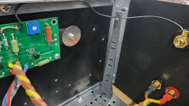
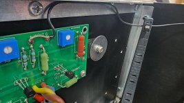
Here's what the input signal wiring looks like with 130mm wire posts holding the wire up and away as much as possible. I'll keep posting wire post designs to the link below for anyone with access to a 3D printer. They attach securely with a single M3x12mm bolt and nut (slide into the slot in the print).
https://www.diyaudio.com/community/threads/wire-post-for-wire-mangement-3d-print.410484/
I shall see how these PLA+ based posts hold up being right next to heat sinks that could reach 60°C. I have hope they will hold up just fine, but will report back after empirical testing. Worst case, I'll have to reprint using ABS material to avoid thermal deformation.
Attachments
Last edited:

Nice novel idea birdbox to wire management! I love the expertise you bring from a 3D printing standpoint!
Thanks for sharing,
Anand.
Thanks for sharing,
Anand.
I would think thermals would be more optimum with the power FET's mounted at about one third of the heatsink height, measured from the bottom, or at least below the belt line.
That is true.I would think thermals would be more optimum with the power FET's mounted at about one third of the heatsink height, measured from the bottom, or at least below the belt line.
Best,
Anand.
re: position on the heatsinks. All above are correct re: ideal positioning for heat dissipation. For those considering... I don't have every version of the Modushop chassis, but they're commonly used in builds. If you're using a UMS heatsink in a common Modushop chassis with a baseplate...
For those that are 'baseplate flippers' be extra cautious of clearances / spacer height choices. For those that are not baseplate flippers... still ... be cautious of clearances... it's snug. For all... be cautious / wary of how you will adjust your bias / offset and surrounding parts mounted to the baseplate. As you've read... the bias / offset require some patience, and ideally they would be set to final adjustments at thermal equilibrium. Think how you'll get your screwdriver in and out while making tiny adjustments with the lid removed quickly.
tl;dr - Try to 'mock assemble' everything to check clearances before final assembly.
If it's not too hot... and if you're not trying to eke out every mA... I'd personally mount it toward the top... and not worry about it, particularly if you're not in the camp of crank it up until just before she starts to melt. Again... YMMV and each choice is up to the individual based on the chassis they're using and layout that works best for them. However, ideally, yes... mount them toward the bottom IF you can successfully adjust properly.
I would think thermals would be more optimum with the power FET's mounted at about one third of the heatsink height, measured from the bottom, or at least below the belt line.
Things that could have been brought to my attention...Yesterdaaaay! Lol. I'm kidding.
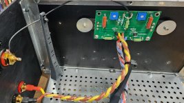
I actually looked at placing the boards lower when I was doing initial layout, but the boards don't fully match up with the UMS. There's 4 holes to mount the amp boards, but they do not all work with the UMS mounting pattern as only 2 will line up. I was scratching my head for a while, then just decided to mimic 6l6's approach. In fact, a lot of what I did mimicked 6L6's layout. That was intentional. No thermal concerns were mentioned with his build, so that's the route I went, and I'm not too worried about it. If it's not cooling efficiently enough, I'll just flip the amp upside-down, problem solved 😉 (or dare I bring up feedback control loops for actively controlled forced convection babysitters again?)
My gut tells me the difference in temps will not be all that significant, but I really have no clue as a noob here and my gut instinct is wrong 50% of the time. Darned convection never fully there when you need it, and then shows up when you don't want it (like the wind chill factor in MN when it's -16°F). This all sounds like a test problem in a thermal dynamics class. It's a good data point for a beginner like myself to account for going forward. At least I can avoid the math as it can be easily measured by flipping the amp inverted and measuring the difference in temps. I shall report back with results.....but first, gotta get this thing biased up tonight. Very excited to hear what it can do. For now, I got this distraction called "work" that's getting in the way of all my F5m fun.
Ya it's fine. As with many things there is "optimum - best practice" and there's "good enough". I have drills and taps and not afraid to use them, but it's not a task I look forward to doing, for sure. I have a "stubby" tuning tool for adjusting a potentiometer in tight quarters... and so on. My monoblocks look like Swiss cheese with all the mounting holes, having housed probably 10 different configurations (maybe more, can't recall) over the years. Homebrew, pre and post "UMS" mounting specs.
Looking forward to your report...
Looking forward to your report...
@birdbox, I wouidn't loose sleep over your amp board position.
One of my class A amps with bias current of 1A8 has the left channel mosfets mounted on the HS 1/3 up from the bottom. But the boards are not mirrored, so in order to keep the signal input towards the rear of the chassis the right channel is flipped upside down putting the mosfets HS mounting 1/3 from the top.
After the amp reaches temp.... 1ºC difference between channels.
just flip the heatsink on other side 😉I'll just flip the amp upside-down
^ Which results in positive vs. negative H2? 
 ^^
^^Is that a modushop chassis from store? It looks nice and long in the picture. Very niceHaha. I’m awake now. Cooking one channel.
That is the way I do it. Someone suggested it and it always made sense, the heat rising upwards. I follow build instructions I'm told, and that one is gold with me. At least a touch under the "belt line" should be term of art.I would think thermals would be more optimum with the power FET's mounted at about one third of the heatsink height, measured from the bottom, or at least below the belt line.
That just answered my question! 3U300.Initial setting of both channels went well. Now monitoring Iq and DC offset in the main rig with music playing. It sounds very good. Silent background.
During initial setting, 1.4A Iq resulted in 55C at the warmest part of my 3U300 sinks. I’ll get it settled in the main rig at stable Iq and offset, then see where I can get with a little fan action on the sinks.

In the middle of bias/offset right now. I noticed that Papas article mentions measuring voltage across R6 or R7, but 6L6 mentioned measuring across both? I have 4 meters going right now, 2 per channel, only using one 0.47 ohm resistor. Should I be measuring across both 0.47ohm resistors for a good average?
Additionally, 0.8V is mentioned in the article for 1.4A, but that's confusing me. 0.8V should be 1.7A correct across 0.47ohm.
I'm trying not to break this thing before I at least get to hear it 😉

[Edited to get units right and update photo.]
Additionally, 0.8V is mentioned in the article for 1.4A, but that's confusing me. 0.8V should be 1.7A correct across 0.47ohm.
I'm trying not to break this thing before I at least get to hear it 😉
[Edited to get units right and update photo.]
Last edited:
Looks like you have the correct number of DMMs 
The best way is to measure bias current, across either R6 or R7, and DC offset across the speaker terminals.
Make sure you understand how to use Ohm's Law to convert voltage across an 0.47Ω resistor into amperage. So 0.8V is too much, better dial it back. Also make sure you are using the recommended thermistors for the current that you want to have. Higher bias current (1.4A) needs different thermistors than what was listed in the original BOM.
Well, at least I am ok on the heatsinks. Temps are 50°C. I'm ok with 1.7A bias personally. I assumed the 1.4A max was for 3U chassis heat sinks mentioned in the article. Am I incorrectly making that assumption? Is there another reason 1.4A is max bias?
I'll dial it back anyway for now. Looks like the kit from the store came with the 10ohm thermisters, so I'll either have to dial back bias significantly, or get ready to desolder, and wait for new parts from Digikey. Shucks, everything was so stable.
Thank you for the quick follow up. I shut it all down and ordered 5ohm thermisters. Looks like I'll have to hit the pause button for a while and continue to practice my patience.
[Edited for update]
Last edited:
Heatsink temp is Ok. But the thermistors are not the ones recommended for high current. Plus, standard FETs don't really benefit from the extra current. They will just get hot to little avail. Swap in the correct thermistors (4.7Ω), then try 1.4 or 1.5A and see how that sounds.
I'm running my F5m at 1.5A, and +/– 29V with a set of high transconductance FETs that perform better at higher Vds and bias current.
I'm running my F5m at 1.5A, and +/– 29V with a set of high transconductance FETs that perform better at higher Vds and bias current.
- Home
- Amplifiers
- Pass Labs
- F5m kit