Regarding Transformer Chassis Seat post #877: I'm going to make a post in the swap meet to avoid clogging up this thread.
https://www.diyaudio.com/community/threads/transformer-chassis-seat-antek-300-400.410463/
https://www.diyaudio.com/community/threads/transformer-chassis-seat-antek-300-400.410463/
Last edited:
I have an Antek 500VA 5218 transformer mounted vertically in my 4U chassis. Has about a 1/2" clearance.question for someone with experience: will a Antek 400VA transformer fit vertically inside the 4U deluxe chassis for this build? I presume so, but.....

Looks like prices for chassis at Modushop have gone up by 20-30% recently. That's going to make using a smaller chassis a lot more appealing to folks. Does anyone have other suggestions for options that are similar to the 4U chassis for a F5m? The Chinese chassis on ebay are affordable until you factor in the $100-$200 in shipping fees.
Well you can disregard my prior post (#884). I was informed by a reputable source that the prices on the website were updated show the total price with VAT included (not including shipping obviously), so shipping to other countries will show less once an address is added for checkout purchase.
Wheeew. I love Modushop chassis, so was worried I missed out on the prior site pricing. Regardless, probably best to get your chassis ordered now as prices eventually will go up as time goes on. I'm making my wish list now!
Wheeew. I love Modushop chassis, so was worried I missed out on the prior site pricing. Regardless, probably best to get your chassis ordered now as prices eventually will go up as time goes on. I'm making my wish list now!
@birdbox yes, the way of the world, I’m afraid! One can still get a Modushop chassis for really darned good pricing if they go for a modded “iron” based version. I did exactly this for with substitutions for the UMS 4u heatsinks and a deluxe back panel. Don’t need the 10mm front panel nor additional drillings or weight savings.
Alternatively, I still enjoy the idea of found, franken, or DIY chassis. I know they are more of a pain, but love thinking up cheap as chips ideas for heatsink chimneys, surplus scrap wall amps, or cobbling together active systems. It fits with the broader values of the F5m, equally a F5c(heap) according to Nelson’s video. Was previously thinking of a bolted together active 80/20 t-slot chimney monstrosity, but a bit too exposed for my 2.5 year old. (If anyone is in the LA area and needs 6 feet of t-slot, happy to provide!)
That said, a proper UMS 3u chassis sounds like a chefs kiss. Soon enough.
I hope someday to have a CNC machine for chassis mods, however, for now, I love the fact that Modushop does a such a fantastic job with a "turn key" chassis for all these wonderful amp designs we all enjoy building.
Haha. I’m awake now. Cooking one channel.On page 7 of the revised F5m build doc. Just one correction: With 0.47 ohm source resistors, I believe 1.4A bias would render a voltage of 0.66V.
I think Papa was just making sure we were awake.

Attachments
Initial setting of both channels went well. Now monitoring Iq and DC offset in the main rig with music playing. It sounds very good. Silent background.
During initial setting, 1.4A Iq resulted in 55C at the warmest part of my 3U300 sinks. I’ll get it settled in the main rig at stable Iq and offset, then see where I can get with a little fan action on the sinks.

During initial setting, 1.4A Iq resulted in 55C at the warmest part of my 3U300 sinks. I’ll get it settled in the main rig at stable Iq and offset, then see where I can get with a little fan action on the sinks.
Attachments
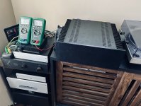
With a 5 inch x 10 inch x 1 1/4 inch heat sink pair I can achieve about .9 amp of bias with temps around 55C. Repurposed Antec 50 amp power supply case. Is there an easy solution to make the bias set less touchy? (single turn Bourns)
I don't advocate one way or the other... I used the single turn pots supplied with the kits for this build, and with some patience, it was what I'd consider a very simple and stable process to set the bias / null the offset. I've used 25-turn pots in a lot of builds also.
With that said... I've used some of the Bourns 3339 series 4-turn pots to good effect. I haven't the foggiest of clues re: hysteresis or any of the actual technical pros / cons of the various pot designs and materials. I just figured the 4-turn pots may be a nice 'tweener'. They are a bit more (at least when I bought them) than comparable single-turn or 25-turn pots, but ...
Check footprints etc. YMMV ...
Initial setting of both channels went well. Now monitoring Iq and DC offset in the main rig with music playing. It sounds very good. Silent background.
How much DC offset do you measure and how long does it take to stabilize?
When adjusting, I left each channel at about 20mV DC offset because I was happy with the Iq measurement at about 660mV. One gets a feel and a rhythm to how each pot affects the values and how the circuit responds with the heatsink. Once warmed up to around 1A of Iq (470mV), my amp seemed to settle with 10 minutes between little increases of current. So once I was content, I left the pots alone. It took me about an hour to set one channel and be satisfied with the results.
Later when I fired up the amp from cold, the DC offset started at about 50mV and steadily went down to about 20mV as the amp warmed up. Everything settles within an hour. All benign values and behavior. I didn’t experience turn on or off thumps.
Like Nelson advises in his articles, take your time and make small, incremental adjustments. Patience rewards the builder here.
I think i'll keep it. funny how you can tell within a few seconds that a device is going to sound good.
I haven’t built either one yet (have the parts just not the time) but methinks the B1R2 with the F5m is about as “pure” as you can get, with no added fillers or preservatives. If anyone has tried this combination, I would love to know your impressions.
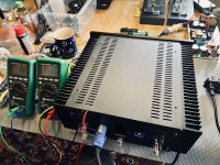
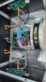
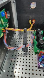
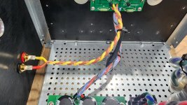
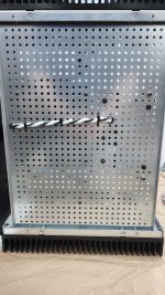
Power Supply rails checked out at ~+/-25VDC unloaded using DBT (dim bulb tester) with 150W incandescent followed by autoformer to ramp up. After verification of good DC rail voltage I let the capacitors drain (or attempted to), but then realized a 3W 10ohm resistor would help speed things along when used appropriately (and carefully).
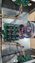
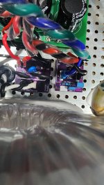
Got the wiring from PSU to amp boards done. Transformer primary/secondaries probably need to be shortened, but I had already crimped on the spade connectors, so left them as big loops to be fixed later. Still need to connect signal input wires.
Im using @rhthatcher boards for mains inrush with CL60 thermisters and rectifiers with snubber resistors and capacitors for AS-3218 per Quasimodo posts from other users.
I'm going to carefully read power up instructions tomorrow and hopefully get bias and offset dialed in.....then.....glorius music.
Me thinks March is officially "F5m Month" from now on 😉
Stay tuned....
Attachments
Last edited:
- Home
- Amplifiers
- Pass Labs
- F5m kit