In his usual "kind educational words" Mark told usin fact exactly where he would consider spliting a CRCRCRC between 2 boxes ;-)
Lots of clever thinking behind a simple result, as usual...
The usual ones, plus some bonus such as the the ombilical contributing to one of the R and, to answer what I presume is your question, having some Cs on the receiver side helps having a so called hard (low impedance) PS close to where it is needed.... modelling all that with the appropriate Rs could possibly result in a filter feeding... a battery like PS (low ESR caps in parallel for example). Another bonus is that the quality of the tranny gets in that case less and less important etc.
Well, just thinking out loud after a nice glass, late at night, while browsing on my favourite website... after having spent the eve rebuilt a very similar home made PS "2 box set" for my pre-preamp (RIAA amp) ;-)
Enjoy music and learning and building on DIYA!
Claude

Could somebody please let me have the between centers measurement for the output device holes as I'll be drilling and tapping my own heatsinks? Thanks.
Could somebody please let me have the between centers measurement for the output device holes as I'll be drilling and tapping my own heatsinks? Thanks.
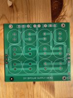
The UMS pdf on this page https://diyaudiostore.com/pages/universal-mounting-specification will serve you well if you are drilling and tapping yourself. As said the mosfets will fit across 120mm and the board mounting holes are 80mm x 40mm. All multiples of 20mm, very neat and clever.
As the captain has so rightly said, here is the direct link to save to your computer devices or print.
Best,
Anand.
Best,
Anand.
3U300 Mini is my favorite! We love a challenge that induces colorful exhortations.3U Mini on the right looks like it would be a real challenge

very interested.If someone need a second psu board to build dual mono I don’t need mine. Pm me if interested. You pay the shipping and it’s yours
FWIW, I had to drill my heatsink holes too.Could somebody please let me have the between centers measurement for the output device holes as I'll be drilling and tapping my own heatsinks? Thanks.
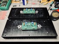
I laid the PWB down on the heatsink, and used it as a template for the 4 mounting holes. Its easy if nothing is installed in the PWB.
After drilling and tapping those holes, I loosely mounted PWB with the 2 FETs (without soldering), and located their mounting holes.
Used a punch to locate the holes in the middle of the circle made for each hole.
I have one done so far, and it fits fine, 2nd one will be made over the weekend.
Transaction completed.Sold to Hilzarbeiter!
You have PM.
Let me know if p/p fails.
Thanks
I have one as well that I don't need,however I don't need the caps and thermistors as well I would throw in the board if you pay for the caps,thermistors(4), and shipping Cost would be as per digikey and no profit.Hi Ylab, I will take it.
Vinay
The second half should be in the remote box, yes. I used to do tube ps like that. As close to the output transformer as I could get it. Worked for me.
Russellc
Russellc
Hi @oreo382 , I could use an F5m PS board if it is avaiable. Please PM me with the details. Thanks!I have one as well that I don't need,however I don't need the caps and thermistors as well I would throw in the board if you pay for the caps,thermistors(4), and shipping Cost would be as per digikey and no profit.
Good idea to stop before you get too tired and make a dumb mistake, been there done that at 1am with a tube amp, my little 450Vdc B+ really woke me up….i did the mistake of telling my wife..😂Good stopping point for the evening. Hopefully, my F5m will be singing tomorrow.
- Home
- Amplifiers
- Pass Labs
- F5m kit