

Hmmm..
Are we going to discuss electric fields vs magnetic fields?
They happen to require different shielding techniques and materials.
ZM anticipated my question
Are we going to discuss electric fields vs magnetic fields?
They happen to require different shielding techniques and materials.
ZM anticipated my question
you can practically take that picture I linked as illustration for both - electric and magnetic phenomena inside one Donut
simply because Donut is electromagnetic apparatus
simply because Donut is electromagnetic apparatus
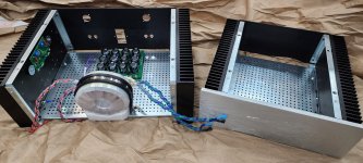
A little more progress on chassis population tonight. Still a ways to go though. Thanks to 6L6 for posting the pics of your build. Your inspiration helps my motivation. Also, thanks to Zen Mod for his poignant comments about chassis size. The 4U deluxe on the left leaves plenty of space to work, while the 3U Mini on the right looks like it would be a real challenge to fit everything in without a lot of cuts, scrapes, and cursing 🤬. A wise choice for a nooby like myself.

Attachments
Coming along nicely!A little more progress on chassis population tonight. Still a ways to go though.
As I mentioned in the M2X thread, "B" field (magnetic) flux line interference from a big energized structure like a power transformer won't be controlled with a wimpy thin sheet of metal. Your first line of defense should be distance, as much as possible to something that may be sensitive to it. A little bit of thin metal, braid, or foil on something (connected to ground of course) might help in situations with an EM wave that is "E" field in nature.
So, distance is 1 key, but I am not clear as to potential advantages of how vertical vs horizontal mounting effect the circuit.flux line interference from a big energized structure like a power transformer won't be controlled with a wimpy thin sheet of metal.
Regarding vertical vs horizontal mounting:
Moving more of the transformer away from sensitive areas of the channel boards is most likely to help prevent EM interference. So simple distance is the thing.
Moving more of the transformer away from sensitive areas of the channel boards is most likely to help prevent EM interference. So simple distance is the thing.
Good discussion by all. As Tungsten has correctly said, this becomes even more important with 'naked' iron (M2X pointed out by William above) that doesn't have much shielding (unless you create your own with mu metal), especially with designs like the M2X.
The general rule of thumb is if you place two loops of wire next to each other they can/will inductively couple through their mutual inductance and the amount of inductive coupling scales with the loop area. So if you're looking to minimize 60Hz induced hum issues, one needs to look at both the generator/"offender" end and in the receiver part of the system. The vertical mounting helps in that regard since you can move it AWAY from the input area of the main amp board.
Best,
Anand.
That's right. The signal iron / power iron can "talk to" each other, and we don't want that. An example being someone trying to build a "tight and compact" M2X where you just can't get the two far enough apart. Vertical mount should be good all the way up front. Noise issues many times are more likely a new builder with dual mono arrangements with a rat's nest of wires, nothing twisted, input cabling draped near something noisy, ground loops... etc. The simple F5m built as intended should be easy peasy. And Jim's build guides are fantastic.
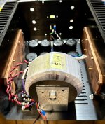
An example of vertical mounting with an Antek 300VA transformer.
This chassis is nearly identical internally to the DIY Sony VFET (lottery) chassis. A 400VA transformer would just squeak inside, but this one is easier to work with.
This chassis is nearly identical internally to the DIY Sony VFET (lottery) chassis. A 400VA transformer would just squeak inside, but this one is easier to work with.
Attachments

I remember distinction as any grounded conducting material (incl. nonferrous metals) should work to shunt e-fields. B-fields, OTOH, need ferrous shields (iron, mu-metal, et. al.). The diagram above shows B-fields in toroids to be (mostly) internal to donut, though, so maybe that's why they're generally not dealt with for such trannnies.
Another solution would be putting the transformer in a separate box.
There's lots of discussion about doing this in other threads, but one suggestion I've read about this solution is that the transformer shouldn't be alone in one box and the CRC filter in another with a cable connecting the two. Rather, the first bank of caps should be in the box with the transformer, or at least an additional bank of caps.
Is that indeed the case? (I don't know). Why?
simple as - keep it furthest possible, buy screened if possible, mount it vertically if possible
making strict recipes from generalizations is never clever
now, keep in mind that this amp is much less sensitive to Donut mounting/position than, say, Papamps having signal xformer in FE
anyway, you'll all decrease amount of obsessing ..... simply with mileage
making strict recipes from generalizations is never clever
now, keep in mind that this amp is much less sensitive to Donut mounting/position than, say, Papamps having signal xformer in FE
anyway, you'll all decrease amount of obsessing ..... simply with mileage
Last edited:
I'd be inclined to put about 50% of the total filtering capacitance in the upstream "satellite" box with the transformer, and about 50% of the total filtering capacitance in the "downstream payload" box where the active amplification circuitry is located. I'd also begin a design using the working hypothesis that 33% of the total series resistance (the "R" in CRCRCRC filtering) belongs in the trafo satellite box, and 67% belongs in the downstream payload box containing the amp guts. Having some amount of resistance upstream, means you get some amount of HF filtering at the sharp corners of the ripple waveform. Where the rectifiers turn off and on. Keeping some amount of HF noise out of the umbilical cable and out of the downstream payload chassis.
Transformer mounted vertically because it makes for the greatest room to work in this chassis. And I had that neat mount on hand.
😎
😎
All this talk about interference from your toroid. I have never had an issue with hum in any of my amp builds (same chassis ,different boards). 500va Antek transformer mounted laying flat approx. the middle of the amp with the ps board in front of it. Chassis size close to a 4u. Amp board inputs to the rear of the amp. I dont know,lucky or is there something to my layout.
Thank you for the explanation, Mark!I'd be inclined to put about 50% of the total filtering capacitance in the upstream "satellite" box with the transformer, and about 50% of the total filtering capacitance in the "downstream payload" box where the active amplification circuitry is located. I'd also begin a design using the working hypothesis that 33% of the total series resistance (the "R" in CRCRCRC filtering) belongs in the trafo satellite box, and 67% belongs in the downstream payload box containing the amp guts. Having some amount of resistance upstream, means you get some amount of HF filtering at the sharp corners of the ripple waveform. Where the rectifiers turn off and on. Keeping some amount of HF noise out of the umbilical cable and out of the downstream payload chassis.
I'd be inclined to put about 50% of the total filtering capacitance in the upstream "satellite" box with the transformer, and about 50% of the total filtering capacitance in the "downstream payload" box where the active amplification circuitry is located. ...
Hmm? Why are you splitting the filtering that way?
How about 99% of the filtering in the remote box and then use a shielded twisted cable to transport the DC. You could put a simple filter in the receiving end if you wanted, in case you had RF noise around the umbilical cable. This way you'd be getting rid of the line noise far away from the analog amp circuitry.
The one part that might be interesting is the noise on the AC ground itself.
- Home
- Amplifiers
- Pass Labs
- F5m kit