Glad you figured it out. You should celebrate by getting a MC cartridge for use with the Pearl3…you will not regret it.So now The P3 with 4 each 2SK209's functions as expected. Built with Pioneer Kit recommended part values.
Absolutely correct.My brain had to keep working, even when I walked away from the Pearl. I have used a source follower to help a tube phono feed a much lower impedance preamp. Thinking about U1:A, it can take much of the current demand from it's drive circuit if a N type depletion MOSFET is added at the output. The source would feed through R9//R22+R10. Done right it would not upset the input fets or mess with the output RIAA balance.
Thoughts hbtaudio?
However, under normal operating conditions, it is not at all clear whether the low-resistance load is a real problem. Wayne will certainly have tested all this and confirmed it with measurements. Either you trust the design proposal or you measure it yourself. I actually assume that with a suitable U1:A there will be no saturation or other negative phenomena.
Just stubbornly follow the kit. And, if you want to, put it through its paces later. Technical specifications - publish the results.
We can always make it better or worse.
")
Addendum:
We could, of course, examine all this beforehand using measurement technology and also simulate it (the existing models are now first-class) - I assume Wayne Colburn has also done this extensively.
What would Douglas Self say about all this? He already had a good look at the current integrated operational amplifiers.
@DualTriode
I am pleased that everything is now working as you wanted it to.
Regards,
HBt.
Thank you hbtaudio!
For my listening, as built per the original kit, it sounds wonderful. My critical listening is with a HOMC. I need to obtain a standard MC and see how it sounds. For the MC world, the gain is just right.
I was just seeking, maybe for some users with MM issues, a slight benefit in reduced gain.
For my listening, as built per the original kit, it sounds wonderful. My critical listening is with a HOMC. I need to obtain a standard MC and see how it sounds. For the MC world, the gain is just right.
I was just seeking, maybe for some users with MM issues, a slight benefit in reduced gain.
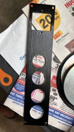
I started to get my cabinets prepped for the Pearl 3 in the similar 2 chassis format. Did the major work of back panel drilling and now need to find thinner aluminium sheets (my cabinet back panel is only 2mm thick) to hold the Aviation type 3 pin plug on the IEC socket hole. Also if someone can point me to the Neutrik 3 pin socket will be helpful as I usually get those Aviation 2/3 pin plugs from Amazon.
Attachments
A little more information on my setup is that I am using MC cartridges in my system typically or low output Grados.
When testing I haven’t seen any problems driving the 220 Ohm feedback resistance, the OPA1656 does say it can drive 100 mA though. Sometimes I choose a part or value because they exist in large quantities in the stock room. Feel free to choose your own values if you want but rest assured if you build it with the kit and get the parts in the right spots soldered well this will work every time and sound pretty good.
When testing I haven’t seen any problems driving the 220 Ohm feedback resistance, the OPA1656 does say it can drive 100 mA though. Sometimes I choose a part or value because they exist in large quantities in the stock room. Feel free to choose your own values if you want but rest assured if you build it with the kit and get the parts in the right spots soldered well this will work every time and sound pretty good.
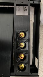
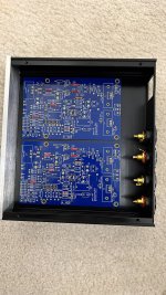
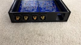
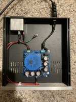
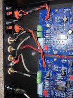
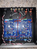
Here are a few pictures - pretty basic I think. I do have floating wires coming off the holes above the xlr pads on the PCBs that I thought I needed but do not have hooked up. You can see where I had a chassis ground lug that I was trying to hook up to the umbilical shielding, phono ground lug, etc.
Chassis are not stacked and about two feet from each other in my system. I haven’t had time yet to try grounding the XLR outputs differently but will try soon.
Chassis are not stacked and about two feet from each other in my system. I haven’t had time yet to try grounding the XLR outputs differently but will try soon.
That’s not right. Photos please.
XLR… I floated the jacks from the chassis and wired all three wires/pins to the PCB. It was quiet in two different builds, but it’s not exactly the way you're “supposed” to do it. In a perfect world you connect only + and - to the PCB&Jack, and pin 1 is connected to chassis. Experiment to see what’s quietest.
Do you have the two chassis stacked (or next to each other) when in use?
Attachments
Thanks Wayne!A little more information on my setup is that I am using MC cartridges in my system typically or low output Grados.
I think this is the crux of the matter. The input stage was originally designed by you (in /for the ONO) as an MC PrePreamp and today, due to the general call for more GAIN, it is experiencing an all-over negative feedback, which allows us to adjust the resulting amplification factor within quite wide limits.
Logically, the operational amplifier (no matter which one) has no load problem with 2k2+10Ohm.
I myself don't find it challenging to develop an MC-compatible input amplifier, but with an MM it looks completely different - as we all know.
Well, amplifying the signal of an MM generator linearly by a factor of 23 is perhaps (a little bit) borderline on some days.When testing I haven’t seen any problems driving the 220 Ohm feedback resistance, the OPA1656 does say it can drive 100 mA though. Sometimes I choose a part or value because they exist in large quantities in the stock room.
So your recommendation, if I'm interpreting it correctly, is:
to use Texas Instruments (BurrBrown) Superduper OPA1655 (single).
Of course, this is DIY with your /my own head.Feel free to choose your own values if you want
That is also true again.but rest assured if you build it with the kit and get the parts in the right spots soldered well this will work every time and sound pretty good.
greetings,
HBt.
Attachments
That is also a good interjection - and above all, quite (in each individual case) easily verifiable.considering signal swing at output of said OP, even 100R is hardly any load
100 ohms is really no problem for a power amplifier or a headphone amplifier.
The matter also depends a little on the frequency, i.e. also on the time characteristic (a function of t) of the signal.
Let's be clear, not every OP is suitable.
And as far as the level is concerned, simply connect an oscilloscope to the output of the first stage and take a close look at the signals, using an analog scope of course.
And you can also use an envelope curve,
play a record.
Here are a few pictures - pretty basic I think. I do have floating wires coming off the holes above the xlr pads on the PCBs that I thought I needed but do not have hooked up. You can see where I had a chassis ground lug that I was trying to hook up to the umbilical shielding, phono ground lug, etc.
Chassis are not stacked and about two feet from each other in my system. I haven’t had time yet to try grounding the XLR outputs differently but will try soon.
Looks to me, as you have mounted the RCA cables the wrong way?? Screen on cable as "hot" and inside wire as "cold"??
Attachments

Samuel Groner has put a lot of great information out into the audio design world. One of my favorite audio design authors.
Since the Pearl 3 project is all about low noise / high gain amplification, you may want to check out his article in Linear Audio vol 3, "A Low Noise Laboratory-Grade Measurement Preamplifier" for a deep-dive into low noise design. It's lengthy, but masterful. Only if you want to really geek out on low noise design theory though!
Another standout work of his (IMHO) is his commentary on Douglas Self's Audio Power Amplifier Design Handbook - lots of well reasoned, insightful thinking.
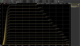
In the meantime, I have carried out some simulations regarding the load behavior. Yes, you can already see marginal differences between 2230Ohm and 230Ohm - but they are not really significant. I think any fears can be put to rest with our still quite tiny levels. But you shouldn't expect a THD of better than 0.03% for the highest tones either.
In addition to our luck, the 75µsec time constant causes a natural band limitation.
In addition to our luck, the 75µsec time constant causes a natural band limitation.

But many years of experience and hard engineering skills. Surely that's what you mean?I wish and believe in Wayne's luck, but nothing here is result of his luck

Finished mine over the weekend. PSU still waiting for the right cable and IEC inlet… Everything runs as expected. Very nice, dead quiet.
Putting it through it’s paces with some moving coils I got kicking around. Driving an Aleph P1.7 into an Aleph J that’s powering a pair of LS3/5a’s.
Couldn’t be happier. Thanks to everyone involved in this project.

Putting it through it’s paces with some moving coils I got kicking around. Driving an Aleph P1.7 into an Aleph J that’s powering a pair of LS3/5a’s.
Couldn’t be happier. Thanks to everyone involved in this project.
- Home
- Amplifiers
- Pass Labs
- Pearl 3 Burning Amp 2023