This appears to be the case, even though I used USB isolators. I might need to build a linear PSU... Oh FFSI got great advice regarding the effect of the digital part of my equipment...
Try to turn of the usb / server
Just my 2 cents
I'll try a couple of thing and will update you

50/60Hz or 100/120Hz hum or is it noise?Friends!
I need a fresh eye. Maybe you can spot something I missed. My P3 was amazing and dead quiet. Barely any noise and no mains hum. `Then, out of the blue, one day there is a significant amount of mains hum. Nothing was changed.
Short the input, is the hum still there? If it's gone you have an issue with the wiring from turntable to P3.
Careful dressing of power supply wiring
Adequate power supply filter caps
Ground loop breaker
If it's noise, could be oscillating JFETs in which case you would put a gate-stopper resistor or a small ferrite. BF862's I know are susceptible to oscillation.
I need a servant and a lab - Improvised conditions at home
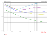
Please bear in mind in all comparisons that this is a fairly free table setup and shielding is completely absent.
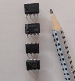
A sample from hundreds of old operational amplifiers DIL8, gathering dust in my chambers. Really random, I just made sure not to plug in the really good stuff.
The green curve corresponds to THD_1kHz, yellow THD_3kHz ... in percent of course.
DC offset:
741 < 53mV; 356 < 12mV; 071 < 5mV; 5534 < 500mV;
SNR the same for all OPs!
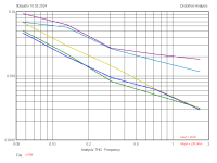
Please bear in mind in all comparisons that this is a fairly free table setup and shielding is completely absent.
A sample from hundreds of old operational amplifiers DIL8, gathering dust in my chambers. Really random, I just made sure not to plug in the really good stuff.
The green curve corresponds to THD_1kHz, yellow THD_3kHz ... in percent of course.
DC offset:
741 < 53mV; 356 < 12mV; 071 < 5mV; 5534 < 500mV;
SNR the same for all OPs!
Attachments
It might be worth double-checking that all your chassis parts are making good solid ground connections with each other. Someone earlier in the thread suggested removing the powder coat on the top / bottom panel screw hole chamfers using a countersink. If you want to go bootstraps & suspenders, you could add a ground wire from the rear GND post to the amp bottom panel, with star washer to get a good bite into the exposed metal.Friends!
I need a fresh eye. Maybe you can spot something I missed. My P3 was amazing and dead quiet. Barely any noise and no mains hum. `Then, out of the blue, one day there is a significant amount of mains hum. Nothing was changed.
Setup:
Marantz PM-14S1 SE amp
Oppo BDP-105D player
Avid Ingenium turntable
A server connected via USB to the Oppo
Things I have checked until now:
Interconnect cables
Power cables (Oppo has a loose cable and moving it increased the noise. Replaced, the hum stayed)
Optical inspection of the inside of P3
Moved cables around (nothing, the hum is independent of how cables are laid)
I'm happy to hear any recommendations as I'm honestly baffled. Perhaps I missed something.
You can also try opening vs shorting the umbilical shield to preamp chassis link to see if breaking or closing that connection favorably alters a nuisance ground loop in the system.
Attachments

Last edited:
I need a servant and a lab - Improvised conditions at home
Hello,
The supply chain has been shipping the QuantAsylum QA403 lately. This is a quality analyzer epically for the price.
More overhead margin possible in MM mode? Yes, adding 5.6 Ohms to R8 reduces gain by 3.7dB, overhead margin increases by this amount. You can now listen to the Telarc "1812 Overture" without worry of blowing up your P3:
Looks like you are also getting greater than 50dB gain at 1kHz with the as supplied kit part values.
I am also getting greater than 50dB gain, which cuts into the overhead margin regardless of overall system gain. It is getting close to the 15V + / - supply rail(s).
All,
Am I mistaken thinking that it is easier to increase the P3 gain and that we are are already close to the lower limit of adjusting the gain lower. Is it more difficult to adjust the gain because the equalization is included in the feedback loops. You know, change one and it effects everything else.
Is the P3 any better or worse than other Phono Pre's at recovering from overloads due to pops clicks or the like?
Thanks DT
Last edited:
Changing the gain via R8 does not affect the RIAA compensation. It does add a bit of noise which is largely irrelevant for that inherent in an MM cartridge.
For MM, you only need 40dB of gain, so you have a lot to work with if overhead comp is an objective.
For MM, you only need 40dB of gain, so you have a lot to work with if overhead comp is an objective.
It's so easy:

If there could be a problem in this respect, then only with the linear first stage, if. Take a close look at my test circuit diagram, I use 30Vdc and the "Arbeitspunkt" at outputview is +17V (and 20mA). Apart from that, I'm still not satisfied with the base voltage divider R2 & R3 ... But shall we continue to nag about the big hit P3? The more I think about the circuit, the more often I end up with the P1.
😉
Regards,
HBt.
Not a bit better or worse than other comparable dimensioning and topologies.All,
Am I mistaken thinking that it is easier to increase the P3 gain and that we are are already close to the lower limit of adjusting the gain lower. Is it more difficult to adjust the gain because the equalization is included in the feedback loops. You know, change one and it effects everything else.
Is the P3 any better or worse than other Phono Pre's at recovering from overloads due to pops clicks or the like?
Thanks DT
If there could be a problem in this respect, then only with the linear first stage, if. Take a close look at my test circuit diagram, I use 30Vdc and the "Arbeitspunkt" at outputview is +17V (and 20mA). Apart from that, I'm still not satisfied with the base voltage divider R2 & R3 ... But shall we continue to nag about the big hit P3? The more I think about the circuit, the more often I end up with the P1.
My wife will lose patience with me at some point and would say: get it done at work.Hello,
The supply chain has been shipping the QuantAsylum QA403 lately. This is a quality analyzer epically for the price.
😉
Regards,
HBt.
@Donaldspace - nice build! I like the concept of P4 with linestage in one box. Do you have pix of the inside?
You are not mistaken about the first stage.Am I mistaken thinking that it is easier to increase the P3 gain and that we are are already close to the lower limit of adjusting the gain lower.
The main problem is the 10 ohms of the R8, the common source resistance for Q1,2,3,4 is a real problem for the U1:A. If the first stage is to have an amplification factor of 10, you load the OP with 90+10 = 100 ohms. It doesn't really like that, because the (resulting) >7mAp (worst-case scenario) to be supplied is already straining its internal structures, and that at the end of the audio range of all places. The only remedy here is to use a lowoutput MM or other jFets or a completely different input circuit, or a different setting of the operating point of the parallel jFets - or an MC and a little more OLG.
For the second stage change both resistors R15 & R8 to adjust the gain.
The challenge is still to determine the most suitable OP for the first stage, or to justify why Mr. X is the best choice at this point. Also why R10 of all things should be 22kOhm or R11 of all things 1MOhm. By the way, R10 (||R1) represents the load for the cascode, a current flows - U1:A is a current-to-voltage converter.
Sorry for the typo.For the second stage change both resistors R15 & R8 to adjust the gain.
Correct ist "R15 and R18" simultaneous.
Sorry for the typo.
Correct ist "R15 and R18" simultaneous.
Are you sure about R15 and R18?
To me they look like they are part of the active RIAA compensation in the op-amp feedback loop.
True if you change R15 and R18 you change gain but you also change the RIAA equalization while you are at it. If you change one thing you change everything.
I have been playing with the Hagerman Bugle "Phono Pre" where the RIAA equalization is passive, the gain can be adjusted with a resistor or 2 without affecting the RIAA equalization.
Thanks DT
About 100% sure.Are you sure about R15 and R18?
Yes they are, but they also adjust the gain.To me they look like they are part of the active RIAA compensation in the op-amp feedback loop.
And that's exactly why you have to adjust the value of both at the same time.True if you change R15 and R18 you change gain but you also change the RIAA equalization while you are at it. If you change one thing you change everything.
I have been playing with the Hagerman Bugle "Phono Pre" where the RIAA equalization is passive, the gain can be adjusted with a resistor or 2 without affecting the RIAA equalization.
R15 and R18 at the same time and in the right ratio. Take a close look at my example table for C=100nF.
gladly,Thanks DT
HBt.
If one wants to analyze the Pearl3 proposal and describe its function, one encounters 2 times 2 construction sites.
The first construction site can be equated with the first stage, the second is the second stage, each subdivided at least once more.
I don't really want to do this, but a few points make me pull the trigger as a result of various (careless assumptions) statements.
You yourself have already stated that Q9 is miscast with a J112 etc. but do you believe the following: "Q9 biases U1 into class A".
U1:B works internally unchanged - for sure.
There are too many construction sites. The general recommendation can only be:
Don't think for yourself and buy Jim's kit. Be carefree and happy.
Even if it works quite differently than you would like to believe. And yet you could learn so much here, from scratch and with hands and feet - if you wanted to!
This person did a nice job summarizing the detailed equations for the non-inverting op amp feedback topology:
Andy C: Phono Preamp Design Using Active RIAA Equalization
If you want to cut 'n try some practical component values (with actual op-amp models), I posted an LTspice deck of the EQ stage earlier in this thread.
Andy C: Phono Preamp Design Using Active RIAA Equalization
If you want to cut 'n try some practical component values (with actual op-amp models), I posted an LTspice deck of the EQ stage earlier in this thread.
I haven't taken pics of the interior yet. Too busy listening to it, or should I say, Through it. It doesn't color the sound. Because of the WLS, I used the Flex-Reg power supply with fixed 18V regulators. The P3 uses the supplied parts eveywhere except the input loading remap that let me set 10K load to the cartridge. I'm thinking about how to implement another WLS for a Tape loop output, and a Tape/Source selector. I think the 50VA Flex-Reg PSU should be able to handle the added load. The PSU is on the right, with a steel barrier with small holes in it to partition the chassis for magnetic seperation. There was just enough room for the Pearl 3 boards and Wayne's Line Stage in the rest of the chassis. I may have to stack the WLS boards for the tape loop... Selector switch is a Grayhill unit with gold/silver contacts. Volume is an Alps RK27 50K unit from Audio Express.
I am also dealing with 120 Hz buzz / hum after finally getting my kit assembled. I am using the modushop chassis combination and ground scheme in the plans. I’ve tried various other grounding combinations (shorting phono ground lug to chassis directly, grounding power cable shield to RIAA chassis, etc. Also ground lifted my entire system from the wall and ground lifted individual components to see if that would help. Still have it with the turntable disconnected and the inputs shorted. I thought maybe using the XLR outputs would help but that made it worse (likely due to increased gain). One specific question - should I ground the XLR output ground tabs to either the chassis or the ground of the XLR output? Any other ideas?
The amp seems to sound very good otherwise and when playing the signal from the turntable seems to overpower the hum.
The amp seems to sound very good otherwise and when playing the signal from the turntable seems to overpower the hum.
@wayne and All,
I have seen the errors of my ways.
Previously while I was setting the series output voltage of the new Keysight bench power supply I entered 19Vrms thinking that in series it would be double that for the + / - series output, it was not. Now the output voltage is corrected to + / - 19 Vrms for a total of 38Vrms. Each 7815 and 7915 on the P3 PCB has volts to regulate 15Vrms + / - at the output of each.
So now The P3 with 4 each 2SK209's functions as expected. Built with Pioneer Kit recommended part values. Thanks to @6L6
Input is 5mv
Gain is 50.39dB
output volts is 1.653Vrms
THD+N is 0.004%
SINAD is 87dB
The above measurements were taken with APx555 analyzer. My expectation is that the limting factor will be the Turntable MM cartridge.
See the updated P3 FFT with 2SK209 Jfets below.
Thanks DT
Do you have recessed ceiling lights?I am also dealing with 120 Hz buzz / hum after finally getting my kit assembled. I am using the modushop chassis combination and ground scheme in the plans. I’ve tried various other grounding combinations (shorting phono ground lug to chassis directly, grounding power cable shield to RIAA chassis, etc. Also ground lifted my entire system from the wall and ground lifted individual components to see if that would help. Still have it with the turntable disconnected and the inputs shorted. I thought maybe using the XLR outputs would help but that made it worse (likely due to increased gain). One specific question - should I ground the XLR output ground tabs to either the chassis or the ground of the XLR output? Any other ideas?
The amp seems to sound very good otherwise and when playing the signal from the turntable seems to overpower the hum.
My brain had to keep working, even when I walked away from the Pearl. I have used a source follower to help a tube phono feed a much lower impedance preamp. Thinking about U1:A, it can take much of the current demand from it's drive circuit if a N type depletion MOSFET is added at the output. The source would feed through R9//R22+R10. Done right it would not upset the input fets or mess with the output RIAA balance.You are not mistaken about the first stage.
The main problem is the 10 ohms of the R8, the common source resistance for Q1,2,3,4 is a real problem for the U1:A. If the first stage is to have an amplification factor of 10, you load the OP with 90+10 = 100 ohms. It doesn't really like that, because the (resulting) >7mAp (worst-case scenario) to be supplied is already straining its internal structures, and that at the end of the audio range of all places. The only remedy here is to use a low output MM or other jFets or a completely different input circuit, or a different setting of the operating point of the parallel jFets - or an MC and a little more OLG.
For the second stage change both resistors R15 & R8 to adjust the gain.
The challenge is still to determine the most suitable OP for the first stage, or to justify why Mr. X is the best choice at this point. Also why R10 of all things should be 22kOhm or R11 of all things 1MOhm. By the way, R10 (||R1) represents the load for the cascode, a current flows - U1:A is a current-to-voltage converter.
Thoughts hbtaudio?
I am also dealing with 120 Hz buzz / hum after finally getting my kit assembled. I am using the modushop chassis combination and ground scheme in the plans. I’ve tried various other grounding combinations (shorting phono ground lug to chassis directly, grounding power cable shield to RIAA chassis, etc. Also ground lifted my entire system from the wall and ground lifted individual components to see if that would help. Still have it with the turntable disconnected and the inputs shorted. I thought maybe using the XLR outputs would help but that made it worse (likely due to increased gain). One specific question - should I ground the XLR output ground tabs to either the chassis or the ground of the XLR output? Any other ideas?
The amp seems to sound very good otherwise and when playing the signal from the turntable seems to overpower the hum.
That’s not right. Photos please.
XLR… I floated the jacks from the chassis and wired all three wires/pins to the PCB. It was quiet in two different builds, but it’s not exactly the way you're “supposed” to do it. In a perfect world you connect only + and - to the PCB&Jack, and pin 1 is connected to chassis. Experiment to see what’s quietest.
Do you have the two chassis stacked (or next to each other) when in use?
- Home
- Amplifiers
- Pass Labs
- Pearl 3 Burning Amp 2023