Please help me connect the dots, I see the calculations that lead to 75 watt dissipation, but what does the 75 watt diss. tell me?Dissipation is 48V*1.57A = 75 watts on


I’m a Newbie every time I start a new project. 
So the devices are dissipating 75 watts, I assume this then factors into the devices spec's and the necessary heat sink?it heats
https://www.diyaudio.com/community/threads/store-heat-sinks-thermal-numbers.392902/
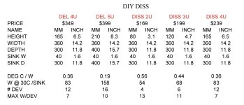
The file Nelson posted at this thread is helpful for the dissapation questions/comments. (Converting Watts needed to be dissapated to estimated temp rise of heat sink)
I've attached a screenshot of the file as it helps align what's being said here by others and it's a great topic to learn.
I'm considering using a 3U Mini-Dissapante for the F5m (package shows up tomorrow!), but want to be sure I can adjust the bias to my liking without running into heat dissapation issues. I'm sticking with 55°C heat sinks in a home with average of around 70°F during most of the year. For those days that are so hot my indoor temp creeps into +80°F, I'll just have to use a "babysitter" with the smaller 3U chassis if needed (babysitter = forced convective cooling using some sort of fan:
https://www.diyaudio.com/community/threads/babysitter-for-papas-koan.186554/)
[Edited to add image from Nelson's post and additional comment on babysitter]
Attachments
Last edited:
Please let me know if what I am writing comes across as snarky or confrontational. It’s a 2 way medium with these forums so I can’t tell compared to a real live conversation like on Zoom or Facetime for example.Please help me connect the dots, I see the calculations that lead to 75 watt dissipation, but what does the 75 watt diss. tell me?
Okay, on to your question which is a good one.
On the last pages of the F5M article, Pass gives examples of chassis sizes and heatsinks and that is for a good reason. If one increases the bias current, then one has to also take into the consideration the increased heat dissipation so that the output Mosfets are within their safe operating zone and for general safety purposes. A safe rise is about 25 degrees C above ambient. 30 degrees is also okay as Pass used. You’ll see that various sized heatsinks have ratings of degrees C/watt. So for example at a 75 watt dissipation if one used a 2U heatsink, it will rise 42 degrees C above ambient, for a total of 67 degrees C which is much too toasty. I try to aim for a max of 50-55 degrees C for safety. This dissipation is divided amongst the output transistors which there are two. The large chassis used on post 626 will definitely accommodate this (it appears to be a 400mm deep, but I can’t tell if its a 3U, 4U or 5U height). The heat rise won’t be as generous compared to my extreme example of using a 2U.
Hopefully that helps!
Best,
Anand.
Last edited:
Thanks @poseidonsvoice, very helpful. No worries, your posts are meant to be helpful, if they aren't for 1 they likely are for another. I didn't get the sense that you are ever talking down, just offering help.
Same question though, does a larger heat sink tend to be less prone to temp fluctuation, seems logically 😉
Same question though, does a larger heat sink tend to be less prone to temp fluctuation, seems logically 😉
It’s the 5U 400mm deep. Which I was planning to use for another amp build but decided I couldn’t wait for a small case for this amp. 🙂. The case is massive overkill for this amp. The sinks are at about 40C right behind the amp while the amps are way up at the top.
That’s another good question. I haven’t had that experience personally. What I do find is that larger heatsinks take time to thermally stabilize. So I try not to make any hasty judgements about the heat or warmth of a heatsink until a good hour has passed (I also use an infrared Fluke to measure these things as well as the old timey test, my hand!). 50-55 degrees C for me is plenty warm and puts a smile on my face that my amp is being put to good use.Same question though, does a larger heat sink tend to be less prone to temp fluctuation, seems logically
For smaller heatsinks, they heat up much more quickly.
This may affect biasing methodologies different from what is used in the F5m but I will try not to obfuscate this thread by mentioning those ideas. I leave that up to the reader…look up Pass M2, M2X, etc…
Best,
Anand.
Makes sense, there is a sweet spot for size. What got me wondering is there seems to be a lot of heat sink on the modushop cases.
Possibly related question to heatsink size: how important is it for the output devices to be thermally coupled? Specifically, if the heatsink is oversized, would it be more like each output device were on its own heatsink instead of sharing a sink with a common temperature? I’ve wondered about putting each device on a physically separated heatsink in a mono block chassis, but designs usually separate the left and right channels rather than the N and P.
You want the output pair to be thermally coupled together, to minimize offset drift.
Makes sense, there is a sweet spot for size. What got me wondering is there seems to be a lot of heat sink on the modushop cases.
Nelson Pass: "Let's just say it outright: There's no such thing as too much heat sinking. "
Another concern is the efficiency of the transfer of heat from the transistor case to the heatsink. I like to measure the case temperature at the washer/bolt point to get as close to the Tc as possible. The junction tempurature rating in the data sheets is un-measurable since it is internal within the transistor case. Remember, there is never too much heatsink.
So, if I understand, there is no such thing as too much heat sink, that being said it might take longer for the amp to reach optimal temp.
, that being said it might take longer for the amp to reach optimal temp.My methodology of picking a chassis for Class A amps is, buy the biggest one can afford at the time.
If your building the F5m as a first project, chances are your going to get hooked and build more. The chassis is the single most costly component and would be nice to reuse down the road for the next build, thats when you'll regret not previously buying the bigger one because this one likes 1A8 bias current. 😉
If your building the F5m as a first project, chances are your going to get hooked and build more. The chassis is the single most costly component and would be nice to reuse down the road for the next build, thats when you'll regret not previously buying the bigger one because this one likes 1A8 bias current. 😉
When you start cranking up the juice above 1A/ch you will want to use higher
current Thermistors or power resistors on the supply filtering.
current Thermistors or power resistors on the supply filtering.
- Home
- Amplifiers
- Pass Labs
- F5m kit