I built the SUPRA amp in the eighties and i liked it a lot, very quiet, but one of it's less desirable traits is the high input capacitance of 280pF, a bit higher than the recommended capacitance for many pickups. How high will the input capacitance be for the proposed 5 transistor in parallel input?
That is a legitimate question:
How did you come up with this somewhat absurd, frightening value? Just under 300pF lead to almost 1/2 nF with the connection line capacitance! Have you looked into the input with a measuring bridge?
Crap, now I have to measure it (with my circuit). This much too high load capacity for any MM system scares me a lot, even if I know theoretically that this value cannot be correct - you never know 😱.
Regards,
HBt.
( I actually wanted to do something other than measure today. )
- I calculate and simulate exactly 2.2pF for the NPN-PNP-NPN variant. The 19-transistor version therefore has around 11pF plus the obligatory 47pF Styroflex.
- for the PNP-NPN-PNP version I calculate and simulate exactly 4.5pF. The 19-transistor version therefore has approx. 22.5pF plus the obligatory 47pF Styroflex.
- for the original SUPRA, my simulation also confirms the calculation of approx. 36pF.
I built the SUPRA amp in the eighties and i liked it a lot, very quiet, but one of it's less desirable traits is the high input capacitance of 280pF, a bit higher than the recommended capacitance for many pickups.
How did you come up with this somewhat absurd, frightening value? Just under 300pF lead to almost 1/2 nF with the connection line capacitance! Have you looked into the input with a measuring bridge?
Crap, now I have to measure it (with my circuit). This much too high load capacity for any MM system scares me a lot, even if I know theoretically that this value cannot be correct - you never know 😱.
Regards,
HBt.
( I actually wanted to do something other than measure today. )
Measurments
Oh yes,
I just saw that Elektor themselves state the 280pf in their technical datasheet of the SUPRA 1982. That's really interesting and now I've quickly measured it:
With a simple measuring bridge directly at the input (but also one with a relatively high input level, at f=1kHz), Cx is exactly the calculated 36pF during operation.
That is amazing.
Under real operating conditions with a function generator, oscilloscope, various source impedances and 50mVpp as level, Cx at 53.1kHz is exactly 44.5pF.
I have no idea how Elektor came up with this house number, maybe they didn't take all the parasitic capacitances into account ???
Thanks @MartinX for the hint.
I hope this has largely put the issue Cx to bed.
😉
Last edited:

Marcel won't like it,
but the SNR for a short-circuited input and a typical MM input level is >120dB !!!
Unfortunately, my free and flying measurement setup is not suitable for simulating real operation, the interfering 50Hz alone make a correct measurement between door and hinge impossible. But the theoretically / practically determined 123dB with short-circuited input of the EQ, let me look completely reassured into the real future.
Actually, the thing should be shot noisy without end. But it doesn't do that at all - strange, why does this circuit simply not do that?
#
I have to shield the EQ properly and carry it to the lab - unfortunately Haudegen (our friend from the neighboring thread) has fallen out of favor with the CEO and now it will be difficult to come up with the very latest reference equipment, all the big names have been lost.
😢
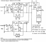
I built the SUPRA a few years ago with my own PCB layout, the normal version as shown in Elektor and one with single transistors. The specification of 280pF for the input capacitance always seemed strange to me and was already questioned by others in the SUPRA thread: https://www.diyaudio.com/community/threads/bc550-bc560-very-low-noise-riaa.91497/saw that Elektor themselves state the 280pf in their technical datasheet of the SUPRA 1982. That's really interesting and now I've quickly measured it:
With a simple measuring bridge directly at the input (but also one with a relatively high input level, at f=1kHz), Cx is exactly the calculated 36pF during operation.
In later LTSpice simulations I got an input capacitance of 7 pF for the single transistor version and 25 pF for the parallel connected transistors. With the same type of sim on the OREAD I now get 13 pF input capacitance for the single transistor circuit, 59 pF on the one with transistors connected in parallel. Maybe my simulation approach for this is wrong. Could you explain, perhaps with circuitry, how your measurement or simulation works?
I can do that, of course, but we'll see when I have the time. Postponed is not canceled 😊.
At the moment I'm reassured by your confirmation; we can all rest, assured that - my method of determination follows the same principle as the metrological determination of the input capacitance.
I measured (if you want to call the determination process that!) today on the SUPRA with the original Elektor board.
I think the right time to explain the entire metrological determinations is when I have fitted OREAD with your board.
Regards,
HBt.
Thanks for the "SUPRA" LINK, I would never have found it myself 🙄.
#
23 pages, oops
No user has answered the question you asked there, that's very poor.
I will answer it later, but first a "yes". With your modest means, it is also possible if you can determine the frequency of your sine exactly.
In the beginning, even Germany's most famous bachelor Holger Barske got involved. He should actually know - or are these advance praises on my part for this qualified self-builder and author? A likeable guy.
Last edited:
Also, in the schematic they connected a 4.7pF (4p7) capacitor to the input, which doesn't make sense when there's already something around 280pF present. Maybe someone had problems with decimal points back then? 28 pF would be more in line with our measurements/simulations and then adding 47 pF would be fine.Elektor themselves state the 280pf in their technical datasheet of the SUPRA 1982.
Last edited:
Quick answer
How to check Cx size with home remedies?
Our big advantage is that the input impedance is not unknown. We approximate it according to the sketch, Z_inp(jOmega) = 1/ ( 1/R_inp + jOmega*Cx). We have a function generator and an oscilloscope as well as an ohmic resistor at our disposal. With the assumption that Cx, but above all R_inp (the real part) is frequency-independent, we can already get started.
We choose R1 = R_inp (=47kOhm) and thus build a simple voltage divider, we can neglect the internal resistance of the generator (if it is significantly smaller than R1, 50 Ohm is it).
As a first step, we choose the voltage U_AB sensibly, because we do not want to overdrive the EQ, but at the same time maintain sufficient reading accuracy on our oscilloscope screen. U_AB = 200mVpp from this follows U_CB = 100mVpp -> we obtain an equivalent voltage source with the internal resistance of R_inp || R1 = 23k5Ohm, as well as a source voltage of 100mVss = 35.36mVrms. We check whether this is the case between f=100Hz and f=1kHz. We don't have any sophisticated measuring equipment at our disposal, so we make do with the fact that a simple first-order low-pass filter should be present.
We know neither the phase angle nor the current, virtually nothing but the voltage at the complex input impedance Z_inp, but that doesn't matter. Because now we increase the signal frequency up to /till U_CB from 100mVpp to 70.7mVpp
Now we increase the signal frequency until U_CB has dropped from 100mVpp to 70.7mVpp and note the frequency.
We calculate a C, but not Cx:
C_test = 1/ [ (2*PI*f_test) * (R1||R_inp) ]
We also need to remember and know our measuring equipment and the data of the test leads, probe, etc. typical for a scope is an Rp of 1MOhm in parallel with a known or unknown Cp.
Rp must of course be much larger than R_inp if we want to neglect it, but Cp, all parasitic capacitances that we (unknown) connect in parallel to our test object increase C_test.
Cx is sufficiently accurate = C_test minus the sum of all parasitic Cp's at f = f_test. This is one way to determine Cx at home with simple means and with sufficient accuracy.
Attachments

Last edited:
I suspect that Elektor Cx could have investigated in the manner described above, but in the haste may have forgotten all parasitic influences. Maybe they tried to oscilloscope voltage and current and use XY mode to get the angle information from the Lissajous figure. They may have approximated using the idea |phi| = 45° ... Here you can make more mistakes than you realize.Also, in the schematic they connected a 4.7pF (4p7) capacitor to the input, which doesn't make sense when there's already something around 280pF present. Maybe someone had problems with decimal points back then? 28 pF would be more in line with our measurements/simulations and then adding 47 pF would be fine.
Today we cannot possibly say what the masters of the late 1970s did in the laboratory - but we can measure it ourselves. It is obvious that there must be an error in the publication. But so what; my masters knew exactly what they were doing back /in time then, I remember them very fondly.
Now they have all long since passed away
😢.
The only important thing is:
the Elektor SUPRA 1982 EQ is a well thought-out, great circuit implementation - a timeless classic, easy to use and safe to rebuild.
Last edited:
Dear "Katze",
we need your universal circuit board to give OREAD the breath of life 😇.
In the meantime, I worked through the 23-page corona lockdown thread - tough. I would have expected a reference in the first post to the fact that the circuit was published in a DIY magazine in 1982 - I don't like adorning myself with other people's feathers.
All in all, a tough read after four years of delay. A lot of things remained unanswered, sideshows were created, some things were and are simply wrong, others right.
I like your personal interest in tackling things, starting with the ancient ELO circuit.
Kind regards,
HBt.
The parallel connection of bipolar transistors found a quasi-predecessor in ELRAD issue 01-1980. As an example, it shows how you can use the noise behavior of uncorrelated sources to create a moving coil preamplifier. I suspect that the published circuit and the text are more of an ETI translation than a Hanoverian original.
To save the honor of the SUPRA, it must be noted that the only thing they have in common is a simple parallel connection of two complementary amplifiers and the parallel 2 x 4 input BJTs.
The global and local feedback strictly follows a different concept.
With the SUPRA you also have to internalize that it can process MCs as well as MMs. OREAD can't do that!
Die ELRAD Quelle
As I suspected, the Canadian magazine ETI was initially the source of the German editorial team:
Project 473 by David Tilbrook
"Series 4000, moving-coil cartridge preamplifier"
☕
time!
As I suspected, the Canadian magazine ETI was initially the source of the German editorial team:
Project 473 by David Tilbrook
"Series 4000, moving-coil cartridge preamplifier"
☕
time!
Very interesting, the supposed high input capacitance never caused any problems for me and now I know why, it was never real! So I decided to experiment on my own, I have a DER-EE DE5000 LCR-meter so I simply connected it to my preamp, it was powered on, selected 10kHz frequency and what do i get? The short cable used was 33pf the meter showed 64pf so 31pf left for the input capacitance. I measured the LCR meter with my oscilloscope and it puts out 550mV RMS 10kHz sine wave with these settings, a bit high but not unreasonably high. The preamp output was not connected to anything so I did not explode my tweeters.
Thank you very much. So I wasn't completely wrong. But I let LTSpice do the work and simulated with an inductor instead of a resistor.Quick answer
How to check Cx size with home remedies?......
btw:
the PCBs are in progress. Due to the Chinese Spring Festival + shipping time we will have to wait until the beginning of March.
Thank You.....so 31pf left for the input capacitance.
So my simulated 25pF are reasonable. I have to add the difference as part of the build, PCB copper layer etc.
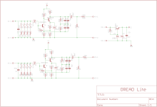
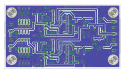
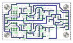
hbtaudio, playing around with Eagle - pl see pcb for Oread-Lite version, referring to your post below -
https://www.diyaudio.com/community/threads/modding-rebiasing-a-2-stage-phono-pre.407948/post-7579969
oread-lite schematic
https://www.diyaudio.com/community/threads/modding-rebiasing-a-2-stage-phono-pre.407948/post-7579969
oread-lite schematic
Attachments
Last edited:
Hello "quadtech",
percy" will be pleased - you have designed a nice layout for his circuit, so it's no wonder that you found the source.
From the discussion thread there, a completely different exemplary dimensioning has emerged - which comes 100% from my brain and is based more on an ancient Valvo dimensioning.
What do we do now with your beautiful implementation? Post it again in Percy's thread!
Here again OREAD light:

Greetings,
HBt.
percy" will be pleased - you have designed a nice layout for his circuit, so it's no wonder that you found the source.
From the discussion thread there, a completely different exemplary dimensioning has emerged - which comes 100% from my brain and is based more on an ancient Valvo dimensioning.
What do we do now with your beautiful implementation? Post it again in Percy's thread!
Here again OREAD light:
Greetings,
HBt.
- Home
- Source & Line
- Analogue Source
- Oread - a DIY MM phono approach