What do you think it's like with jFets or mixed? "Da geht erst richtig die Post ab".Hi...
I just received information that the OREAD PCBs have been shipped.
I assume that it will now take around 14 days, including customs, for the package to reach me.
...
thermal balance:
When I was working with the SUPRA some time ago and, for example, measuring the output voltage offset, I noticed an irregular but persistent +/- fluctuation around the zero point of a few 100µV. It took some time before I realized that I myself was the cause, namely my breath, which was passing over the circuit board and thereby irregularly affecting the temperature of the transistors. In a housing without air movement the “problem” disappears. When testing a board without a case, you can place a towel or something similar over it if necessary. It will probably be similar with the OREAD
Please reserve two boards for me, thank you very much - PN will follow.
🙂
Last edited:
The internal resistance of a source
It is really very large, especially if we have to achieve exobitant voltage amplification.
The core of the SUPRA (representative as a model) can come up with an OLG of > 98dB or even >84dB, depending on how high impedance we close the inner control loop (and we still speak of open loop).
In the first case, the output resistance riq is > 600kOhm with fh > 6.7kHz and in the second practical case (with RF=150kOhm ---> the RIAA network) 115kOhm with 35kHz.
In the CLG case, this value appears to be reduced by the negative feedback factor. It is frequency-dependent. Roughly and simplified we can imagine: (115k ->) 11k5 drops to 1k15 and further to 115Ohm.
In the entire fundamental range, circuits of this type cannot be loaded without (slightly) bending the equalization - as a developer, you have to be that honest.
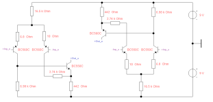
I am attaching the two halves of the balanced SUPRA, the push-pull mode. I'll continue in a moment - remedy is near
It is really very large, especially if we have to achieve exobitant voltage amplification.
The core of the SUPRA (representative as a model) can come up with an OLG of > 98dB or even >84dB, depending on how high impedance we close the inner control loop (and we still speak of open loop).
In the first case, the output resistance riq is > 600kOhm with fh > 6.7kHz and in the second practical case (with RF=150kOhm ---> the RIAA network) 115kOhm with 35kHz.
In the CLG case, this value appears to be reduced by the negative feedback factor. It is frequency-dependent. Roughly and simplified we can imagine: (115k ->) 11k5 drops to 1k15 and further to 115Ohm.
In the entire fundamental range, circuits of this type cannot be loaded without (slightly) bending the equalization - as a developer, you have to be that honest.
I am attaching the two halves of the balanced SUPRA, the push-pull mode. I'll continue in a moment - remedy is near
Attachments
The above applies to all simple circuits of a similar type and always when the last stage is designed to amplify the voltage. Whether single-ended or push-pull operation is irrelevant, the situation can of course be compensated or improved somewhat by a huge quiescent current or taken into account from the outset and a fixed load case provided. Within an integrated amplifier, this can all be done without any problems, but we solve the connection flexibility with a simple additional stage. This could even be included in the universal negative feedback -> an impedance converter as an output stage, but we add it at the back!
Each according to his personal taste, an operational amplifier can be used as well as a simple emitter or source follower, but its input resistance should be 1Meg.
Each according to his personal taste, an operational amplifier can be used as well as a simple emitter or source follower, but its input resistance should be 1Meg.
Attachments
What is the case with OREAD?
Much better than the balanced (single) SUPRA, in a direct (practical RF=150k) comparison:
OLG > 99dB
riqu < 23kOhm
fh > 11kHz
Under certain circumstances and with marginal compromises, we could do without a buffer here. However, some preamplifiers are just too low impedance with their 10kOhm input resistance.
We also set up the openloop case
This applies exactly to the current dimensioning:
OLG > 92dB, fh > 24kHz, ri approx. 10kOhm and therefore, in summary, the OREAD topology is much better than that of a SUPRA.
Regards,
HBt.
This applies exactly to the current dimensioning:
OLG > 92dB, fh > 24kHz, ri approx. 10kOhm and therefore, in summary, the OREAD topology is much better than that of a SUPRA.
Regards,
HBt.
The known and existing topology can also be used as a buffer. It is completely negative-feedback stable as unity gain. In this case, the negative feedback is linear / constant and not frequency-dependent (as we consider it), i.e. the load case is practically meaningless.

HBt.
HBt.
Attachments
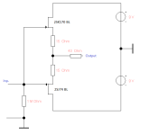
A SRPP circuit.For additional information only
Studer / Revox
used only three transistors in the A78, with 75µA quiescent current for T3.
That's right and you can see it that way. I like my A78 MK2.
I've put the Lego bricks together for a better overview. For the OREAD, however, I will use the discrete jFet OP as an output driver - and to isolate the core from / to the outside.
For all those who prefer a symmetrical design between the rails, because they might find this better for the "Halbschwingung" of the signal, the idea of the SUPRA2024 follows.
Some people believe in something like this or that
😉.
Attachments
Last edited:
Das Rad neu erfunden
My God, at this very moment the basically identical circuit is popping up in another thread - I assure you this is a coincidence and not plagiarism.
😱
My God, at this very moment the basically identical circuit is popping up in another thread - I assure you this is a coincidence and not plagiarism.
😱
The components are all in stock and ordered,
Now there's nothing left but to be patient - I'm curious to see if we can beat the legendary Pearl three with the OREAD approach.
Fellow campaigners wanted
😉
Now there's nothing left but to be patient - I'm curious to see if we can beat the legendary Pearl three with the OREAD approach.
Fellow campaigners wanted
😉
Hi there...
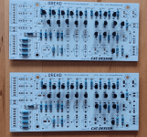
The OREAD-PCBs arrived today.
.jpg")
Now they are ready to be sent on to the DIY people.
If you are interested in the boards: PM me or EMail me
You need one PCB per channel! Size of one Board: 140 x 64 mm
-------------------------------------------------
Shipping:
inside Germany:
one set of two PCBs, including shipping = 16€ with Tracking,
inside EU:
one set of two PCBs, including shipping = 17€ without Tracking; 25€ with Tracking
These are cost prices
Payment via Paypal or Banktransfer/IBAN
--------------------------------------------------
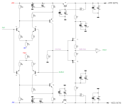
Here again the circuit and layout for this board (rev 04) The layout is shown without the ground plane for better clarity.


Component values, suggestion, (LTSpice OK tested)
(all from the E12 series, at the request of a single gentleman 😉 )
The OREAD-PCBs arrived today.
Now they are ready to be sent on to the DIY people.
If you are interested in the boards: PM me or EMail me
You need one PCB per channel! Size of one Board: 140 x 64 mm
-------------------------------------------------
Shipping:
inside Germany:
one set of two PCBs, including shipping = 16€ with Tracking,
inside EU:
one set of two PCBs, including shipping = 17€ without Tracking; 25€ with Tracking
These are cost prices
Payment via Paypal or Banktransfer/IBAN
--------------------------------------------------
Here again the circuit and layout for this board (rev 04) The layout is shown without the ground plane for better clarity.
Component values, suggestion, (LTSpice OK tested)
(all from the E12 series, at the request of a single gentleman 😉 )
- R1,2 120k
- R3a...e 82k
- R4,5 8k2
- R6a...c 4k7
- R7 2k2
- R8a...c 4k7
- R9 47
- R10 1M
- R3,12 10k
- R13a 47k
- R13b 8k2
- R14a 4k7
- R14b 0
- R15 82
- C1,2 4µ7
- C3,15 100n
- C4,13 220µ
- C5,14 22µ
- C6 2n2
- C8a 47n
- C8b 10n
- C8c 1n
- C9a 15n
- C9b 1n
- C9c -
- C10 1000µ
- Transistors
- PNP BC560C
- NPN BC550C
- Voltage +-15V

The circuit/PCB can also simply be used for single supply:
omit C13, C14, C15, T7, R3
in place C13 install a wire bridge.
PS connector:
minus (-) Pin unused for single supply
Supply voltage then between + and GS(-)
GS: signal ground
GC: chassis ground (groundplane)
omit C13, C14, C15, T7, R3
in place C13 install a wire bridge.
PS connector:
minus (-) Pin unused for single supply
Supply voltage then between + and GS(-)
GS: signal ground
GC: chassis ground (groundplane)
Have you already started to set up our joint experiment, assembling the circuit board with your components?
The stagecoach had delivered two white boards.
Thanks cat.
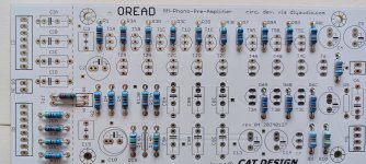
So now it's really starting, I'm curious to see if the circuit idea delivers what it promised us - you only know when the prototype is finished. I will document the assembly step by step with photos, which will certainly ease the fears of other DIYers.
Thanks cat.
So now it's really starting, I'm curious to see if the circuit idea delivers what it promised us - you only know when the prototype is finished. I will document the assembly step by step with photos, which will certainly ease the fears of other DIYers.
Clearly, the first thing to do is to fit the ohmic resistor component.
Color ring code:
0 black
1 brown
2 red
3 orange
4 yellow
5 green
6 blue
7 violet
8 gray
9 white
An example:
yellow violet black brown brown
stands for
4 7 0 * 10^1 +/-1%.
Unfortunately I don't have any magic resistors to hand, but as soon as the next full moon wakes me up, every metal layer resistor will be refined with holy water.
Attachments
? uh, what?Unfortunately I don't have any magic resistors to hand, but as soon as the next full moon wakes me up, every metal layer resistor will be refined with holy water.
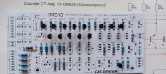
The circuit board offers space for mounting various input resistors and capacitors (selectable via jumpers or external switches) to adapt to the pickup system used.
The entire PCB area of these components is connected to the rest of the circuit via jumper JP1. If you (temporarily) do not want to use these components, jumper JP1 must be removed and the alternative input IA/GS must be used.
If you don't need/want the optional/switchable components at all you can also cut off the area along the dashed line.
@hbtaudio
Apparently you found another way to use JP1.
Magical resistances, use Vishay/Dale or an exorcist, holy water, the full moon ... or whatever, just don't use wire resistors or a carbon layer.
😱
😱
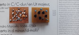
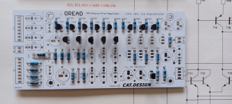
In the next step, we select the bipolar transistors and form pairs that are as identical as possible. A basic quantity of 50 pieces is certainly advisable, as the sample dispersion of the NPNs is considerable. I have fished out all the transistors to around 530 HFE.
And I continue with the frequency response-determining FKPs of our negative feedback network. An LCR measuring bridge is not a luxury now, so today I'm using the Voltcraft LCR-400. After all, toys need to be tested once in a while.
😉
And I continue with the frequency response-determining FKPs of our negative feedback network. An LCR measuring bridge is not a luxury now, so today I'm using the Voltcraft LCR-400. After all, toys need to be tested once in a while.
😉
Attachments
- Home
- Source & Line
- Analogue Source
- Oread - a DIY MM phono approach