4 pin XLR. Clip one side, ring out the wires, and connect on PSU end.
Last edited by a moderator:

I bought the same cable and did the same thing.If anyone is trying to find a quick and easy way to get the recommended Umbilical Canare wire from Amazon, I ordered this and de-soldered the 3 pin XLR connectors to use for custom XLR cables. $19 with free shipping and you just solder on your 4 pin connectors.
https://www.amazon.com/dp/B07VWPPHX6?psc=1&ref=ppx_yo2ov_dt_b_product_details
Now getting some significant hum from the Pearl 3. It's definitely from the Pearl 3, if I disconnect the tonearm cable (VPI lemo connector), hum gets worse. Additionally, if I touch the Pearl 3 RIAA box hum goes down. I will check everything tomorrow and ensure I have good bare metal contacts on each part of the chassis. I wired the unit like the build guide, so I'm not sure what else to check. I'll keep investigating but if someone else found a good way to isolate hum please let me know! Thanks!
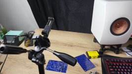
Photos please. Lots of photos.
But from what you are describing chassis continuity is a prime suspect as you surmise.
But from what you are describing chassis continuity is a prime suspect as you surmise.
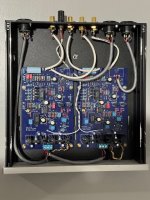
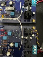
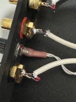
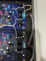
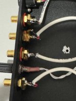
As requested:


Attachments
-
 1706844548036.jpeg100.8 KB · Views: 89
 -
 IMG_0197.jpg81.7 KB · Views: 81
 -
 IMG_0190.jpg100.8 KB · Views: 74
 -
 IMG_0191.jpg82.7 KB · Views: 62
 -
 IMG_0192.jpg93.9 KB · Views: 69
 -
 IMG_0193.jpg71.7 KB · Views: 71
 -
 IMG_0194.jpg47.8 KB · Views: 75
 -
 IMG_0195.jpg71.3 KB · Views: 82
 -
 IMG_0196.jpg52.3 KB · Views: 85
Maybe also check the eight PCB mountings that they don't "short" PCB ground plane to chassis?
It was a topic some posts ago that it might be a good idea to use nylon shims to isolate the PCB ground plane.
As far as I can see the ground plane edge at each PCB mounting hole is gold plated so a metal shim should not touch that gold placed edge.
Also if you use metal standoffs then these standoffs should not touch the ground plane (I use plastic spacers).
Vinyl playback across the LP and cartridge adjustment - alignment vs. distorsion. 🙂
Absolutely No more than 0,004% THD from 20-20 000 Hz.
🙃

Absolutely No more than 0,004% THD from 20-20 000 Hz.
🙃
Useful tools. 🙂
https://alignmentprotractor.com/
”Free turntable cartridge alignment protractors & setup tools”
https://alignmentprotractor.com/
Last edited:
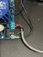
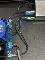
Currently not connected to the RIAA chassis as per build guide. I will try that and report back.@msikk
how is the umbilical shield conductor terminated at the RIAA end?
when it is connected to the RIAA chassis is the hum more or less?
Will check. I thought I checked all those but I'll check again.Maybe also check the eight PCB mountings that they don't "short" PCB ground plane to chassis?
It was a topic some posts ago that it might be a good idea to use nylon shims to isolate the PCB ground plane.
As far as I can see the ground plane edge at each PCB mounting hole is gold plated so a metal shim should not touch that gold placed edge.
Also if you use metal standoffs then these standoffs should not touch the ground plane (I use plastic spacers).
Not at the moment because I pulled it out of the cabinet to open it up. But rest assured, it was connected.Is the ground wire from the turn table connected?
You might consider connecting the inside of the turntable ground post to the DC-in ground, in addition to the audio grounds of the Pearl 3 as you have done. That's what I did. You could try it live with alligator clips & see if you hear the hum drop.
The recessed ceiling lights in my listening room radiate a lot of hum. Originally I thought it was coming from my turntable.
@msikk
Hmmm… this is perplexing. Everything look right, as far as I can tell in the photos, there are some details obscured by lack of resolution, but that’s easy to fix moving forward as needed.
So let’s begin by simplifying things a little, please disconnect the balanced outputs at the PCB and see if that makes any difference.
Also the umbilical at the RIAA chassis should have shield on pin 1, and pin 1 at the XLR Jack would be connected to the tab on the connector itself as shown. You may have it wired as shown, but can’t tell in your photos.
Attachments


- Home
- Amplifiers
- Pass Labs
- Pearl 3 Burning Amp 2023