Oh, haha, yeah. I've been doing that for so long I forgot it's not so obvious. See below for two section views of how to place and cut the tape. Just mark a line 1/2" from the inner edge of the frame, and apply the tape along the line. At this point the tape is still the full 1" wide, and 1/2" hangs over the inside edge of the frame. Then use the blade of a utility knife to slit the tape in half, using the inside surface of the frame as a guide for the knife blade. It cuts like butter with a sharp blade. Tilt the blade ever so slightly toward the surface of the frame and the frame edge will guide the knife to make a perfectly straight cut along the inside of the frame. Then remove the release film from the tape already attached to the frame and apply the cut piece on top of that. Finally, remove the release film from the second layer, and stick the panel in place. You will want to use some kind of guide blocks to position the panel in place before sticking it to the tape. Place it gently on the tape and make sure it's lined up all the way around. If it's not quite lined up perfectly you may just be able to lift it and reposition it, but maybe not as the tape is really sticky!Where I initially got stuck, was on 2 layers of that tape -- I have to somehow cut 100+ inches of the stuff down the center and then layer it? I have a hard time just making a small square that works to stick an exciter to for testing.

Some details are not that critical, as the design is pretty robust. A single layer of tape works fine (instead of two), and it can be a little wider or narrower and have little effect. What's most important isAbsolutely. I'd never say anything about your design without first having executed the build to specs.
- high aspect ratio,
- sturdy and center braced frame,
- damping tape around most of the perimeter.

Hello AndréIn that case they're referring to intermodulation distortion!
Have you had a look to post 11525 and the links?
I don't see the link between IMD and third harmonic. IMD occurs because of the non linearity, not related to one harmonic distortion. If it is could share the source of that?Then again, "self-noise" could mean third-harmonic distortion, which means that the panel is built incorrectly - one of the biggest advantages of DML panels, when built correctly is the very low level of 3rd harmonic distortion.
I agree that DMLs show 2nd order harmonic... and I have to say I don't know why.
A second order harmonic occurs when the output to input relation is not symmetric . An example if a single FET or triode amp stage.
When the transfer is symmetric (example a pushpull stage or a differential), the second order almost disappears.
So in my understanding, third order distortion doesn't mean improperly built.
Having a 2nd order means the displacement is not the same when coil pushes or pulls.
The IMD products are easily visible in a spectrum at the foot of the input frequencies. For sure it is not rattle or flapping noise.Or it could simply be rattling caused by incorrectly mounted drivers, or membranes flapping against mountings, or skins flapping against the substrate. Or, as I eventually discovered after months of heavy abuse, the driver flange itself eventually dismounted from the voice coil.
If there are additional noise in the panel, they will appear in the spectrum not necessary related to the input frequencies.
The real question is from which level can we detect those IMD products or non linearity.
I haven't made many of those spectral contamination or IMD tests but I think it is a good practice able to show quickly if something goes wrong... forgotten the sound they produce is not really pleasant.
Christian
Like I said I'm not really sure what self noise is, but your probably right and it doesn't matter if you measure IMD or THD. I assume self noise means that it is not distortion, then it should be called "self distortion", but is rather an added noise that has no harmonic relation to the signal.In that case they're referring to intermodulation distortion!
Then again, "self-noise" could mean third-harmonic distortion, which means that the panel is built incorrectly - one of the biggest advantages of DML panels, when built correctly is the very low level of 3rd harmonic distortion.
Or it could simply be rattling caused by incorrectly mounted drivers, or membranes flapping against mountings, or skins flapping against the substrate. Or, as I eventually discovered after months of heavy abuse, the driver flange itself eventually dismounted from the voice coil.
Perhaps the is no such thing as "self noise", but there can be some harmonic distortion that is caused by some kind of intermodulation or interference in the plate that will be more or less prominent i different materials, in which case it should probably be called something else.
Like you say in general harmonic distortion is low in DML plates, but if it is different between different materials, why is that?
Hi Christian,Have you had a look to post 11525 and the links?
I did. But not the links.
No, I'm not saying that IMD and 3rd harmonic are the same. They are completely different. Theoretically, IMD is a test for non-linearity under large swing. If f1 is low frequency, and f2 is a higher frequency, then IMD= ∓(f2-f1), and the IMD components appear as side-bands separated by f1 on f2. One can easily identify IMD products as sidebands on spectral analysis.I don't see the link between IMD and third harmonic. IMD occurs because of the non linearity, not related to one harmonic distortion. If it is could share the source of that?
I think it's easier to consider IMD as more related to a doppler effect than to intrinsic non-linearity. A small, HF signal super-imposed on a large LF signal in a full-range cone speaker will unavoidably create a doppler effect on the f2 signal, and therefore IMD will suffer. But I'm splitting hairs. And in any case, DML panels, because of their very large surface area, do not need as much excursion as small cones do in order to move the same amount of air. And therefore the doppler effect (and the implied IMD) should be a lot lower for a panel.
Yes, agreed. Here's exaggerated 2nd harmonic distortion at -12db@90° to the signal. This is a sig-gen waveform for demonstration only.Having a 2nd order means the displacement is not the same when coil pushes or pulls
For this reason I prefer to place foam tape on both the front and back of a panel, and gently clamp the whole assembly in its frame. The other problem, of course, is that exciters drive only from one side, and 2ndHD might be compounded not only by changing of BL as the VC moves in and out of the magnetic field, but also from possibly varying panel/edge/skin differences in the forward vs backward directions. I'll have a design, somewhere in the future, where the drivers would be placed both sides of the panel, but this could create the problem that the motor magnets interfere with each other... drawing board here we come...
3rd harmonic, -12db@0° to the signal.
It's the lack of 3rd harmonic distortion that makes DML panels sound as-if they go into over-drive without warning. Cone speakers generally increase in 3rd harmonic as they get near their excursion limits, and then gradually go into full-blown over-drive. But (thanks to VC driver limits) a DML can go directly into excursion limiting without warning when you over-drive the exciter. This might be why DMLS might not sound "as loud" as cones do eventhough the SPL levels can be measured to be the same. The gradual increase in 3rd HD in a cone can make it sound "louder" than it really is because of the onset of excursion limiting.
What I'm saying in my previous post, is that if a panel is designed incorrectly, especially if the edges are not properly damped for example, then 3rd HD will quickly become an issue because of over-excursion in the panel material. I also suspect that if some the panel anti-nodes are allowed to over-resonate because of improper driver placement, then 3rd HD might also be an issue.
Yes, agreed.The IMD products are easily visible in a spectrum at the foot of the input frequencies. For sure it is not rattle or flapping noise. If there are additional noise in the panel, they will appear in the spectrum not necessary related to the input frequencies.
Rattling and flapping noises will generate spectra all of their own except for the fundamental which would be caused by
the test signal.
Agreed. "Self noise" implies the panels happily making a noise all by themselves when there's no signal driving them. It's a very strange choice of words.Perhaps the is no such thing as "self noise", but there can be some harmonic distortion that is caused by some kind of intermodulation or interference in the plate that will be more or less prominent i different materials, in which case it should probably be called something else.
No Andre. come on .. Not with no signal..😵💫Agreed. "Self noise" implies the panels happily making a noise all by themselves when there's no signal driving them. It's a very strange choice of words.
I take it to mean that certain materials may emit noise under stress due to their internal structure, unrelated to any other factor. I've noticed noise on EPS tests on both unconstrained and constrained panels where there were no other traceable causes. Perhaps other materials do it to a lesser extent but EPS does seem to groan.
The thickness of these panels is not inconsequential, and the physical distortion of the material under vibration could well cause noise of this nature
Eucy
Spedge,I recently showed a picture of a tall panel with the bracing at an angle in red.
The angle will remove most of the standing waves bouncing up and down the panel, dispersing them.
Now I'm having trouble understanding what it is that you believe.
Why would you want to remove standing waves" ? Standing waves are the resonances which you so dearly love and refer to as "DML action".
That being the case, why would you recommend anyone try to remove them?
To be clear (as I think you are aware), I do believe that mitigating standing waves is desirable, but not that angled edges are effective in that regard. I'm just trying sincerely to get a better idea of why you would say you want panels to be able to resonate (or "sing" as you say), but you also want to reduce standing waves, when in fact it is standing waves that are resonating?
Eric
Ok, admittedly I was being a bit facetious, but the point remains: What exactly is "self-noise"?No Andre. come on .. Not with no signal..😵💫
I take it to mean that certain materials may emit noise under stress due to their internal structure, unrelated to any other factor. I've noticed noise on EPS tests on both unconstrained and constrained panels where there were no other traceable causes. Perhaps other materials do it to a lesser extent but EPS does seem to groan.
The thickness of these panels is not inconsequential, and the physical distortion of the material under vibration could well cause noise of this nature
Eucy
Yes, I agree that EPS might emit crackling sounds just before you bend it enough to break it. But this is because the yield strength curves have been exceeded. And this is what might happen when such panels are undamped and the edges flap around wildly.
Other than that, I don't think an audio engineer would identify "self-noise" as a credible term except when referring to the noise floor of a resistor (in which case it's called Johnson-Nyquist noise or maybe Shot noise.)
Don't you think "self-noise" might be an umbrella term used by certain long-term DIYers whose ears are not as "golden" as they think they are, and who decry the use of test gear and theory, and are unable to identify the source of the problem except to provide baseless opinion?
Looking forward to your feedback, Leob!Some xcitement this weekend!
I have a pair of those also, will also test then this weekend against my other panels with Dayton DAEX32EP-4Some xcitement this weekend!
Current setups that I'm "running" now are :
45cm x 70cm, 5mm PPP Celular panel on wood frame, 1x Dayton DAEX32EP-4
40cm x 60cm, 4mm Plywood "floating" on Cotton/Linen Canvas, 1x Dayton DAEX32EP-4 (I think that I've never seen this kind of "setup" here in the forum)
They both sound amazing (to my ears, at least), lets see how those Xcite drivers perform on EPS with Kraft paper on both sides (current built)
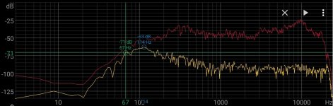
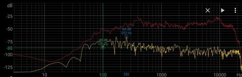
Attached some frequency sweeps plots (done with my phone spectrum analyzer) from my panels, ignore the yellow line (that was the real time feed), the red line are the "tops" registered (panel response).
I currently don't have a reference mic to do some plots, but next time I'll try to use my tablet built-in mic with REW to share with you all my efforts.
Stay tunned ;-)
Attachments
Thanks!Looking forward to your feedback, Leob!
Unfortunately it will not be all fun and games. Soundimports wants me to test each exciter and record a video with the ones with issues for the warranty claim. They will only accept warranty for the exciters that already developed the issue. I guess that is fair enough, but not sure I'm confident to bother mounting those on new plates.
Just removing 64 exciters glued to their plates will probably at least keep me busy most of the weekend 🙁
Hi Leob - are you referring to Dayton Audio exciters here? I assume you have not tried the Xcite drivers yet?They will only accept warranty for the exciters that already developed the issue.
Some pictures would be nice ...45cm x 70cm, 5mm PPP Celular panel on wood frame, 1x Dayton DAEX32EP-4
40cm x 60cm, 4mm Plywood "floating" on Cotton/Linen Canvas, 1x Dayton DAEX32EP-4 (I think that I've never seen this kind of "setup" here in the forum)
Hi pviegas,5mm PPP Celular panel
I’m interested to know more about that material. Do you have any pictures or links to help me understand what it is? Is it like coroplast?
Thanks
Eric
Correct, trying out the Xcite as replacement for the Dayton's, of which some have developed distortion issue.Hi Leob - are you referring to Dayton Audio exciters here? I assume you have not tried the Xcite drivers yet?
It`s alveolar polypropylene.Hi pviegas,
I’m interested to know more about that material. Do you have any pictures or links to help me understand what it is? Is it like coroplast?
Thanks
Eric
I like this ones:
https://hexapan.com/?gclid=EAIaIQobChMI8KHes9HrgwMVggaLCh1QuwDiEAAYAyAAEgJ6dvD_BwE
Excellent, waiting for the report. Good weekend.I have a pair of those also, will also test then this weekend against my other panels with Dayton DAEX32EP-4
(Excelente, venham de lá essas experiências. Bom fim de semana.)
Put together a test plate with a scrap GPS plate where I removed old exciters and put on some X32-4 instead, just using the provided VHB tape.
I improved suspension compared to old plate, so not really and A/B test against the Dayton's, but it is like night and day. X32-4 plates sounds so much clearer and punchier! The old plates really sounds like a smeary mess in comparison...and I used to think they sounded great 🙂
Will do some measurements eventually, but have a lot of work with scraping off old exciters this weekend...
But the difference is so clear I don't need measurements to decide that I'm definitely going to replace all the Dayton's.
If you have a large ply panel, let's say, 6ft x 2ft.Spedge,
Now I'm having trouble understanding what it is that you believe.
Why would you want to remove standing waves" ? Standing waves are the resonances which you so dearly love and refer to as "DML action".
That being the case, why would you recommend anyone try to remove them?
To be clear (as I think you are aware), I do believe that mitigating standing waves is desirable, but not that angled edges are effective in that regard. I'm just trying sincerely to get a better idea of why you would say you want panels to be able to resonate (or "sing" as you say), but you also want to reduce standing waves, when in fact it is standing waves that are resonating?
Eric
This panel will have a sustained resonances somewhere in the low frequencies.
If you are using your panel down to these frequencies the panel will start to act and sound like a drum.
Having none parallel sides will break up these constantly resonating standing waves.
The panels do not have to be clamped , I suggested clamping as a good way mount the panel without any other supports.
With a rigid clamping (my preference) or softer clamping using some other materials between the clamps.
The rest of the panel is free to "sing" without clamping.
There are various dml panel patients talking about none parallel sides and the reasons for them.
I am sure you must have read them?
Steve.
- Home
- Loudspeakers
- Full Range
- A Study of DMLs as a Full Range Speaker