good for you Bas:
All that open space on the top plate leaves you some space for Artistic License. A family crest or logo? An elegant historic symbol. Anyway, room to play and express yourself. A blank canvas so to speak.
Lovely job, the visuals are not quite finished yet
All that open space on the top plate leaves you some space for Artistic License. A family crest or logo? An elegant historic symbol. Anyway, room to play and express yourself. A blank canvas so to speak.
Lovely job, the visuals are not quite finished yet

It does doesn't it. 🙂All that open space on the top plate leaves you some space for Artistic License.
What about LM317 set for 40mA. Have good experience with the RH-84.How about changing the 150ohm cathode resistors to 100 ohms
Surely can try it. I'm not SS phobic so probably worth a try. I've never done that. Should the LM317 be bypassed with a cap? What are its AC properties or frequency response?What about LM317 set for 40mA. Have good experience with the RH-84.
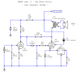
255VBas what are the voltages either side of feedback resistor R10?
Yes. Bypassed. 2 amps I've built use it. RH-84 and the Stupendous PPP.Should the LM317 be bypassed with a cap?
Don't know to be honest.What are its AC properties or frequency response?
Attachments
Thanks Miniwatt!Hi Bas, looks great imho.
They way I have drawn it there is still a large cap from that node to ground. It's just in a different spot on my schematic.One thing I noticed: shouldn't G2 be decoupled with a cap to ground?
But I wonder if there should not be...or maybe if there is an advantage..to add another cap after the screen stopper resistor.
Since none of the knowledgeable people browsing this thread did not suggest any improvements there. I left it alone.
Last edited:
The G2's "dynamic" impedance (meaning how it acts in circuit) is relatively large, compared to its stopper, and anyway shouldn't be bypassed in a way that would defeat the work of the stopper. G2's stopper is intended to be lossy, to damp the small stray resonances in a real amplifier's construction that aren't shown on a schematic.
Things too small to worry about for audio, tiny capacitances and inductances, some in wiring, some inside of components, sometimes in the operation of the valves themselves, can still matter to valves, who are easily capable of working just fine at tens of MHz and don't know that they shouldn't in our application.
Because so much of this just doesn't appear in our schematics and models, it is, like Discretion, always the Better Part of Valour to just include some rudimentary damping around valves, transformers with current cutoffs (di/dt), even cables. Mostly doesn't matter, but cheap insurance against surprises.
All good fortune,
Chris
I see it now, I didn't really look at it and thought that was just driver stage B+ decoupling.Thanks Miniwatt!
They way I have drawn it there is still a large cap from that node to ground. It's just in a different spot on my schematic.
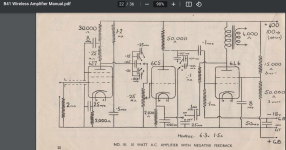
Something else. I wanted to try a different schematic so I ended up with this one by Gerd, because my eye fell on the plate to driver cathode feedback. But did not even read up on it. One of the earliest examples apparently is the RCA 50wattt amplifier (But this is PP so inherently better PSRR. See the disadvantage described later in my post ).
A few threads on this topic can also be found on this forum.
Long story short. I found a page by John Broskie where he says:
Advantages:
1.) Lower distortion
2.) Lower impedance
Disadvantage:
1.) Worse PSRR.
Funny thing is the first time I put it in my main audio system it was quiet. But I had forgotten the cathode bypass cap. So I added that (100uF) and suddenly the amp was noisy. Snipped them out...quiet.
So it appears that added degenerative feedback from removing the output tube bypass cap reduces PSRR to tolerable levels.
My options are:
1. Leave out bypass cap. But that is not acceptable for the sound..amp sounds too thin.
2. Brute force by using the 21st century maida by Neurochrome.
3. Take out the feedback resistor
Or...what else?
Screendumps from Broskie's site.
https://www.audio-talk.co.uk/phpBB3/viewtopic.php?t=4554
Or connect the feedback resistor to the driver anode.
I once heard that feedback to the driver cathode is a bad idea because the cathode is a non linear element. I've never found a good explanation for that, I hope someone here can chime in.
I once heard that feedback to the driver cathode is a bad idea because the cathode is a non linear element. I've never found a good explanation for that, I hope someone here can chime in.
Indeed. That's another option....edging closer to an RH-84 design again.Or connect the feedback resistor to the driver anode..
About PSRR, would not it be better to use a good power supply? I would spend the money on using a choke-input power supply instead of the plate choke.
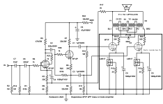
And one could use an LTP as input (not using the second output), then apply feedback to the LTP second input.
Something like this (something I will try for a headphone amp, not a proven design)

And one could use an LTP as input (not using the second output), then apply feedback to the LTP second input.
Something like this (something I will try for a headphone amp, not a proven design)
Hello,
Choke input is my favourite too but it will require another power transformer.
The transformer Bas is using looks like a serious one ( because it has a screen) and most of us don't have a stock of transformers in the attic. In the past one could choose from a wide range of transformers ( German made i believe) available in a brick and mortar shop.
Unless you are building and rebuilding with the same transformer with a wide variety of secundary voltages you will need to spend a considerable amount on the power transformer every time a new idea pops up.
Greetings Eduard
I use this sort of feedback without hummmm, but it is in a PP amplifier where it may well cancel out.
I was thinking if ultrapath connection of the cathode bypass cap would be an option to improve PSRR? I will have a better look at it later...
https://www.tubecad.com/2008/08/blog0147.htm
I was thinking if ultrapath connection of the cathode bypass cap would be an option to improve PSRR? I will have a better look at it later...
https://www.tubecad.com/2008/08/blog0147.htm
No, but you can get a cleaner B+, less rectifier and transformer noise.I like choke input too. But it does not necessarily lower psrr does it?
Worth a try ....I was thinking if ultrapath connection of the cathode bypass cap would be an option to improve PSRR? I will have a better look at it later...
- Home
- Amplifiers
- Tubes / Valves
- Another SE EL84. Following this schematic. Grid stoppers yay or nay?