Can software replicate a good eye? I remain unconvinced.Google software. Pixel 7 Pro.
Chris
Bas what's your psu?
A complete circuit diagram would be most appreciated!!!!
A schematic is more descriptive than words 🙂
"Use a picture. It's worth a thousand words."
"The drawing shows me at one glance what might be spread over ten pages in a book."😍
A complete circuit diagram would be most appreciated!!!!
A schematic is more descriptive than words 🙂
"Use a picture. It's worth a thousand words."
"The drawing shows me at one glance what might be spread over ten pages in a book."😍

Hey Bas what's with the diodes in series with the ez81?
Why not just use as in the data sheet .....it works well this way.I have a table top radio from the 50s that has its original valves in it including an ez in its power supply....These things are tough.
To decouple the output from its driver improves stereo and psrr ....we all want lower noise in our amps.
This things going to sound good....can't wait to hear it
Attachments
Last edited:
It's to protect the rectifier tube. Google Yellow sheet mod. I know it could and will work perfectly without it. But as I wrote in my schematic. I like doing it.
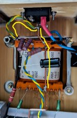
Been following this build. Nice work and tidy build.Wrapped bare multistrand silver coated copper wire through the eyelet of 0 and around the bus. So the ground bus and 0 of the transformer will forever be joined. 😊
I like using the copper ground wire for ground buss like you have.
Not trying to be over critical, just fyi...
I think you need a better solder joint there from my experience using this.
I heat the copper with heat gun and pre tin it while hot and solder my connection immediately after.
Getting a nice tinned spot to solder to that wraps around the copper bus will help insure against a cold joint that could cause trouble later.
Might do it later. Was also thinking about that. Something like 57 ohm 10uF rc.To decouple the output from its driver improves stereo and psrr ....we all want lower noise in our amps.
Glued together. Quick mock-up. Not done yet. Must say...more going on, on one chassis looks better IMO...this looks a bit bland/boring. And a voluptuous 5u4 would perhaps been sexier. Like my decware clone. O well. Clean enough.


Some glamour shots. Since it is an overcast day today. No need to worry about shadows. And no special light @Chris Hornbeck


Hello Bas,
Is the centre tap of the high voltage winding connected to the earth lug from the IEC connector?
What about the screen of the power transformer?
I always read that the iec connector earth terminal should be connected with a short wire directly to the chassis. Also do this with the screen.
You wanna try connecting the choke like always pictured on the bottom of the Lundahl datasheet?
The first cap from Quakkelstein? Paper in oil works excellent in that position.
Greetings Eduard
Yes.Is the centre tap of the high voltage winding connected to the earth lug from the IEC connector?
It is.iec connector earth terminal should be connected with a short wire directly to the chassis.
Also. But all pointless really since my home does not have ground or earth except in bathroom or kitchen.What about the screen of the power transformer?
I might. In a private conversation with someone he found it not sounding as well as the non-common mode connection. 🤷♂️You wanna try connecting the choke like always pictured on the bottom of the Lundahl datasheet?
Nope. It was a gift from a fellow diy'er. Polyprop. Bit short of space for pio unfortunately.The first cap from Quakkelstein? Paper in oil works excellent in that position.
Greetings Bas.
Attachments
Last edited:
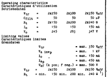
Smoketest done! No smoke! That EZ81 takes a long while to boot up! I love it...like 10 seconds before the 'dial' starts moving.
1st time switched on: No biasing up right, since the EL84's were not drawing current. So faultfinding was in order, as I was looking, I remembered, ah yes, forgot grid leak. Since I had ordered 680k...and they have arrived in the meantime. I chucked them in. Et voila. 2nd time...everything checks out ballpark wize. B+296 a tad high. 30mA on one el84. 36mA on the other. Need to do some matching.
Next up...audio test.
Last edited:
How about changing the 150ohm cathode resistors to 100 ohms and adding a 100ohm pot in series? Should be able to get slightly mismatched pairs adjusted. Test points across the 100 ohm make it easy to measure.
- Home
- Amplifiers
- Tubes / Valves
- Another SE EL84. Following this schematic. Grid stoppers yay or nay?