Yes. But now that you mention it. Not with the EZ81 yet. Sims were done with the 5UG.Have you simulated the power supply in Duncan.
Quickly did sim with EZ81 and real life dcr of one leg as suggested by jcalvarez
Since you said you will split the power supply with 220ohm feeding each channel, you can include the effects of the second channel by inserting a current tap where it will split off. Then just sim for the final current of one channel at the end of the schematic. It keeps it a bit more accurate it seems to me.
John

John

Thank John! Will do. Since I split the driver tube too. (In earlier pic I had them joined, but made em separate later) I'll make em 45mA each (ballpark)
I've been working on a couple of amp designs that use a split dual mono type of power supply such as yours and I found the option of adding the current tap in the middle. Before that I was halving the series resistance or inductance and doubling the final cap values to simulate the two section in parallel. I like the current tap better.
To make the transformer sim even better, click the ellipsis button next to the ohms field and then you can use some actual measured values of resistance and offload voltages for the transformer. It should increase the accuracy of the simulated voltages. Since I don't know the actual resistance and voltage numbers for your transformer I couldn't put them in these examples.


To make the transformer sim even better, click the ellipsis button next to the ohms field and then you can use some actual measured values of resistance and offload voltages for the transformer. It should increase the accuracy of the simulated voltages. Since I don't know the actual resistance and voltage numbers for your transformer I couldn't put them in these examples.
Last edited:
PS. I once translated a practical duncanamp guide by DHT Rob. This guide is the reason I increase my resistance in the secondaries.
https://basaudio.wordpress.com/2024...rsupply-by-dht-rob-translated-by-yours-truly/
I call it a guide because it is not science. There is no guarantee a tuned power supply inspired by this guide is going to lead to a better amp. Feel free to make suggestions and criticize...but it will probably go over my head.
Last edited:
My opinion is not to be very heavily weighted in importance, but I find myself really questioning the premise of this paper. It's stated without any explanation that critical damping is some ideal - why? This same puzzle applies to the Mark Johnson proposed ideal for mains transformer secondary damping. I ask, what magic applies to critical damping in this fairly static location, when an ordinary over damping is more better in any static load perspective?
If there's something there I've overlooked, would be glad to hear it. Can imagine an argument involving the "envelope" of DC current following music waveforms' dynamic draw from power supply, but that's orders of magnitude from what's being considered.
Much thanks, as always,
Chris
If there's something there I've overlooked, would be glad to hear it. Can imagine an argument involving the "envelope" of DC current following music waveforms' dynamic draw from power supply, but that's orders of magnitude from what's being considered.
Much thanks, as always,
Chris
You've not overlooked anything as far as I am concerned.. That is why I tried to "pre-empt" the questioning. Its pseudo whatever you want to call it.
But since reading Lynn Olson...http://www.nutshellhifi.com/triode4.html
On rectifier switching and what it does to the "LCR" tank. I thought this lowering of the current spike could not hurt.
Perhaps I should have summarized my post of adding the resistance by saying: I like adding high resistance to transformes secondaries with tube supplies this is why. Don't know if it makes a difference positively or negatively.
The last thing I want to do is open up a can of worms on something I very well know is nothing more than a guide by a fellow diy'er.
Please forgive me. I misinterpreted post #45 as an invitation to branch out from the origin of the thread, clearly wrong interpretation.
Much thanks, as always,
Chris
Much thanks, as always,
Chris
It's stated without any explanation that critical damping is some ideal - why? This same puzzle applies to the Mark Johnson proposed ideal for mains transformer secondary damping. I ask, what magic applies to critical damping in this fairly static location, when an ordinary over damping is more better in any static load perspective?
Overdamping does unnecessarily increase the power dissipation in the snubber resistor.
In some higher power circuits, that would be a big deal.
Gotta say, your photography would make even a plain girl beautiful. Must be some magic light where you live.
All good fortune,
Chris
All good fortune,
Chris
Google software. Pixel 7 Pro.Gotta say, your photography would make even a plain girl beautiful. Must be some magic light where you live.
All good fortune,
Chris
Silicone. For the choke and caps. Wood glue for the wooden 'planks' to make a little bed for the output transformers.What kinda glue?
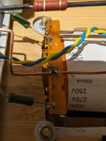
Wrapped bare multistrand silver coated copper wire through the eyelet of 0 and around the bus. So the ground bus and 0 of the transformer will forever be joined. 😊Don't forget to ground the secondary.
Attachments
- Home
- Amplifiers
- Tubes / Valves
- Another SE EL84. Following this schematic. Grid stoppers yay or nay?