Hi all.
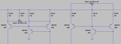
I just noticed that the ltp is running at ~7mA, which is all passing through the wiper of the trimmer..
Personally I think that seems like a lot. I would like to suggest a small change to the current mirror.
I think this should be about equivalent to what you have now. And in case of a trimmer fail, it wont kill the amp.
Edit:
I haven't done a sim to see if it has other side effects. I just think this is safer.
Attachments
Last edited:

Other than the benefit of well behaved DC offset, having the bases see the same impedance makes for a better harmonic profile at low frequencies, believe it or not. Ratios between harmonics and their overall levels. At least I remember seeing this in the simulator a while ago.
What are the mechanisms that affects the harmonic profile particularly at low frequencies, and how low frequencies are we talking about?
Besides the DC offset which is a given, are these claims in the above quotation based on simulations only?
I have also confirmed this phenomenon with OP-AMP. If you configure a gain of +1 by connecting a resistor Rf = 47kΩ instead of directly connecting the feedback, and measure the distortion factor by changing the signal source resistance Rs, a dip will occur at Rs = 47k. Of course, the overall distortion gets worse as the frequency increases, but with a FET input, the distortion decreases as the frequency is lowered, but with a BJT input, it tends to become constant as the frequency decreases. I believe that the distortion at high frequencies is due to the Cob voltage dependence of IPS LTP, and the distortion at low frequencies is due to the Early effect. If so, it is easy to check in Spice, and if you do not specify the IPS LTP Tr spice parameter "VAF" in a discrete circuit, the default value will be infinity. A countermeasure for real circuits would be cascode bootstrapping.
I think it's a good idea to cascode, not only because of that reason.
This will also lower the dissipation in the error amplifier, and therefore lower the delta dissipation, which makes small errors that are probably significant. I don't want small errors in my error amplifier 😉
Again, see the memory distortion stuff by @peufeu . I think I saw an argument about this sort of error making subsonic noise only, because of the big time constant of heat propagation. Being very suspicious, I think it's a good idea to minimize subsonic errors as well. Unless you cap-couple or transformer-couple the output of the amplifier (then you need not worry about subsonic).
It should have three diodes instead of two... above. To give a decent Vce for the differential.
IT is 5 mA through the pot.Hi all.
I just noticed that the ltp is running at ~7mA, which is all passing through the wiper of the trimmer..
Personally I think that seems like a lot. I would like to suggest a small change to the current mirror.
I think this should be about equivalent to what you have now. And in case of a trimmer fail, it wont kill the amp.
Edit:
I haven't done a sim to see if it has other side effects. I just think this is safer.
Yes I see what you mean. I might try your suggestion.
I think it's a good idea to cascode, not only because of that reason.
This will also lower the dissipation in the error amplifier, and therefore lower the delta dissipation, which makes small errors that are probably significant. I don't want small errors in my error amplifier 😉
Again, see the memory distortion stuff by @peufeu . I think I saw an argument about this sort of error making subsonic noise only, because of the big time constant of heat propagation. Being very suspicious, I think it's a good idea to minimize subsonic errors as well. Unless you cap-couple or transformer-couple the output of the amplifier (then you need not worry about subsonic).
View attachment 1247171
I might try cascode.It should have three diodes instead of two... above. To give a decent Vce for the differential.
Do I simply use 1N4148 diodes or what?
Or four?It should have three diodes instead of two... above. To give a decent Vce for the differential.
https://www.diyaudio.com/community/attachments/ka5010clone_sch-png.1053399/
I will not cascode.
There are plenty of amplifiers doing well without cascode.
Simply there is no room left in my schematic. It can not be too crowded 😀
But I have changed the DC-offset potentiometer as suggested.
This was done.
There are plenty of amplifiers doing well without cascode.
Simply there is no room left in my schematic. It can not be too crowded 😀
But I have changed the DC-offset potentiometer as suggested.
This was done.
I agree Lineup - you set out to design a simple, easy-to-build amp - that's a commendable design objective IMV 👍 . There have been a series of massive improvements as a result of a collaborative effort, but you have to be aware of 'creeping elegance' (which my boss always warned me about 40 years ago!) which means ultimately you end up with something altogether different than what you set out to do.
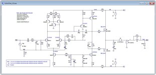
Is there an LTspice schema for this amp - I'd like to run a loop gain plot.
Is there an LTspice schema for this amp - I'd like to run a loop gain plot.
Lineup - Just to reiterate Bonsai, me and several others have said several times, it would be very useful for you to learn how to do loop gain analysis. There are numerous posts on this but you don't seem to be responding to any of them.
Loopgain analysis is absolutely necessary when designing any feedback amplifier. No designer can can be considered serious if he does not use and does not show loopgain analysis. Sorry @lineup that I am that open or maybe harsh, but it is the naked truth. You cannot be considered serious unless you do not learn what is loopgain and how to test it. You have been here about 20 years and it was time enough to learn. It was discussed and lectured in dozens of cases. Anyone these days can put some components into the simulator. But, without a proper knowledge, it does not make him a designer. Just a mere user of SW tool, and that is the big difference.
^ There are lots of references, but when I had a similar question, I started here.
https://www.diyaudio.com/community/...t=Apply an AC input on,Presto: open loop gain.
https://www.diyaudio.com/community/...t=Apply an AC input on,Presto: open loop gain.
Later versions of µcap made it even easier: just insert a loop gain probe and run stability analysis. So handy I even use it in antenna amps with NFB over RF transformers.
Here is how I perform Loop Gain analysis using the Tian probe method. The LT Spice asc, plot and include files are included in the zip file. Hopefully this helps out those trying to learn the process.
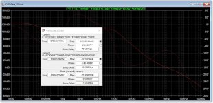
From this example, the gain and phase margins are 22db and 71 degrees with a ULGF of 975KHz.
Disclaimer: I have no formal electronics training and am far from an expert on this. I welcome any input on this approach.
From this example, the gain and phase margins are 22db and 71 degrees with a ULGF of 975KHz.
Disclaimer: I have no formal electronics training and am far from an expert on this. I welcome any input on this approach.
Attachments
Question for the experts:
Douglas Self mentions in the Amp Design book in Chapter 3 that his experience suggests 30db of feedback at 20KHZ is safe and more than 40db is "distinctly risky". What are your thoughts on this?
In the example above, margins looks healthy at 22db and 71 degrees, ULGF looks reasonable at 975KHz, but the feedback at 20kHz is 51db. Is this something you typically look at, and is this an indicator for potential stability issues?
Doug usually speaks about dominant pole compensation. Was it the case? Did he also mention a phase margin? Could you please note in which chapter of his amplifier design book he mentioned it?
- Home
- Amplifiers
- Solid State
- Cello One. Good Amplifier 15 Watt with TMC and Laterals