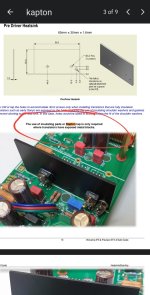
Yes, this is what I used and mounted it on top of the large output transistor like it is shown in the build guide.none is needed now with the updated P/N BD13916S(TU)
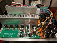
I'm using two ANTEK 40-0-40 400va trans so about +-56vdc. I've also set it up for two separate bridge, filters, and ground break systems.
The ANTEK also has 15-0-15 that is going to be used for two separate speaker protect circuits.
The ANTEK also has 15-0-15 that is going to be used for two separate speaker protect circuits.
I hope no one will assume some vintage BD139 will also work, as they have the collector on the back.none is needed now with the updated P/N BD13916S(TU)
We also have plenty of notes like this in the build guide.I hope no one will assume some vintage BD139 will also work, as they have the collector on the back.
Attachments
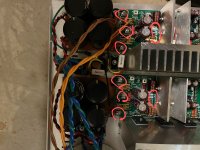
I agree bare wire terminations are not a good idea. Also I’m a bit worried about the heatsink sizes but with lower rail voltage you maybe ok
Please check this point in the build guide.Getting there..
Attachments

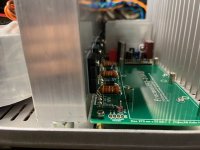
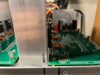
Thanks for all the pointers everyone, Glad you all care to make sure no one makes a blunder. Some of the solder did not go all the way to the top pad but it did fill the via. I did not want to heat the components too much. There is about an 1/8 in clearance between the heatsink and the board.
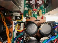
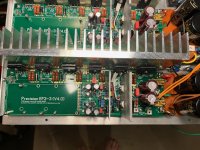
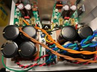
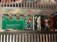
Here are some more pics. I'll post more when I finish the front and the back of the chassis.
Scott
Here are some more pics. I'll post more when I finish the front and the back of the chassis.
Scott
Attachments
I have not touched BOM or build guide in quite a while, I usually build from a schematic supplemented with my own knowledge of the subject, this works very well for me. My amp preforms exceptionally good, is reliable, stable and thermally compensated just the way I like it. Nothing blows up.That’s why it’s clear in the BOM fully encapsulated only have a look.
My question in #2758 is legit and intended to help.

@mainframe99 What kind of electrical isolation was used between Q103 and the HS?
Just Kryonaut, no metal back on Q103 since bias circuit changed
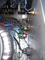
As for the heat sinks, as used in the HiFi2000 Dissipante cabinets. Given the limited thickness of the back plate, app 7 mm, when tapping thread you quickly hit the bottom of the drill hole, which pushes the aluminum material to the top. I found the solution in a Bosch PDB40 table drill with electronic depth gauge and some high-quality thread taps from Exact. I should have bought those years ago, really adds value to the electronics hobby.
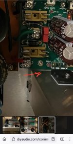
I do see what your talking about. Since I'm not too far into finishing, I'm going to pull the boards and reflow the low spots. I'm using a Black Jack BK30000 solder station, It's for leadfree soldering so it melts the solder very fast so it should be safe not to heat the components up to much.It's hard to see on the photo, but you might wanna check if the solder has reached the topside of the PCB for a good connection.
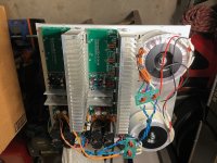
Also if this is a more permanent install shown I would add some cableshoes to the +/-/g on the mainboards 🙂
Thanks for the tips.
Scott
@90scaraudio
With all due respect to your construction, I would like to draw your attention to the size of the heatsink, which I see is small if I judge from my own heatsink. you will have quiescent current stabilization issues at 44mv it will try lower and lower to stabilize it . You must put fan coolers.
With all due respect to your construction, I would like to draw your attention to the size of the heatsink, which I see is small if I judge from my own heatsink. you will have quiescent current stabilization issues at 44mv it will try lower and lower to stabilize it . You must put fan coolers.
Attachments

Nikos, you could perhaps help 90's caraudio (and me), do you know of a decent online source where one could calculate the minimum required heatsinking? I assume the BOM listed size / DIYaudio chassis heatsinks at 300x40x160mm must be sufficient for a 3 pair 70V rail build i.e. 240W 8R/ 430W 4R, as there is no mention otherwise, so how does one calculate the required heatsinking should they be doing a lower voltage, lower power build?
Is it as simple as percentages, i.e. if rails are 54vdc and your power overall is 40ish percent less, can one get away with a heatsink that is 40ish percent smaller?
Sorry, this has probably been discussed ad nauseum amongst more expert members here.
Is it as simple as percentages, i.e. if rails are 54vdc and your power overall is 40ish percent less, can one get away with a heatsink that is 40ish percent smaller?
Sorry, this has probably been discussed ad nauseum amongst more expert members here.
Hi Guy's check out these two videos they might help
Thermal resistance 1
Thermal resistance 2
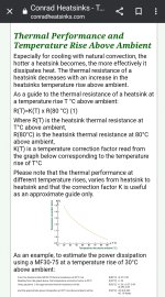
Also check out conrad heatsinks they publish the thermal resistance of there heatsinks and the datasheet has a great explanation and example.
Below is a link that has even more information on the topic.
Thermal resistance 3
Thermal resistance 1
Thermal resistance 2
Also check out conrad heatsinks they publish the thermal resistance of there heatsinks and the datasheet has a great explanation and example.
Below is a link that has even more information on the topic.
Thermal resistance 3
Attachments


Last edited:
I did consider larger. Thanks for your input.@90scaraudio
With all due respect to your construction, I would like to draw your attention to the size of the heatsink, which I see is small if I judge from my own heatsink. you will have quiescent current stabilization issues at 44mv it will try lower and lower to stabilize it . You must put fan coolers.
After rebuilding this... https://www.diyaudio.com/community/...m2-upgrade-with-drm-audio.390068/post-7139604
It has about 90v rails, 220rms x 2 @ 8. I've pushed this thing and it does get warm but I have never been able to kick the fan on.
So looking at the heatsink on that build and I don't think I'll push it that hard and only hooking it up to 8ohm speakers, I figured I'd be safe.
- Home
- Amplifiers
- Solid State
- DIY Class A/B Amp The "Wolverine" build thread