
2 segments Esponential Matched VS Unmatched
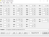
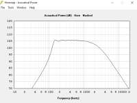
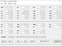
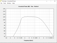
I attach screenshots of two similar horns, one where the two segments (adapter and array) are matched, and one where they are not matched and F12 is made lower to compensate for the higher F23.
I briefly mentioned this two posts above.
Making such compensation (i.e. not matching the two segments flare frequencies) seems to be necessary since the array must be made shorter in order to improve dispersion figures.
These are still way below what is desirable (16-18° angle cell to cell) according to practice derived from Altec design.
I guess this is the price to pay in order to have a usable crossover point of 200/250 Hz. vs minimum 4-500 of the Altec Multicells.
Looks like the unmatched segments display a (marginally) more linear behavior and a LITTLE better low end, so the only real advantage of the "unmatched design" is that the shorter array results in broader dispersion without apparent drawbacks, at least in power response.
I am not sure if there's any drawback to this in other areas.
PS
I guess those who love waveguides, bullet tweeters etc. with sniper-like dispersion will cringe at my efforts to broaden the dispersion.
Attachments
Last edited:
David, I launched Hornresp to reproduce the issue, but now its gone...
Of course it was a saved horn so I did not change any data.
Anyway, I attach the form that produced the error yesterday.
Thanks Gumbo. I have no idea how the corrupted schematic diagram could have been produced, and as far as the height and width profiles are concerned, they are different because a rectangular rather than a square cross-section has been specified. Although the profiles are not the same, the overall area expansion rate and cutoff frequency remain unchanged.
We need to make this phrase immortal.
Something to remember me by perhaps, when I am long gone... 🙂
David, of course I agree the different width/height profiles of the array are due to it being previewed as rectangular. If I would preview it square though, the actual width and height would differ even more from the actual physical array.
This is not at all a problem as far as the CAD design of the array is concerned, because it must be done based on the single cell design, which is perfecty accurate in hornresp.
I wonder (and would like to hear your thoughts about this) if these inconsistencies can make the result of the simulation less accurate/reliable than usual.
In a previous post, Bjorn Kolbrek mentioned that the shape of the profile such as square vs rectangular, or conical width associated to exponential height (i.e. "radials") is not so relevant to power response figures. However in this case we are facing not only a different "shape" of the flare but also of the surface of the four faces which constitute the array.
I do believe that S1, S2 and F12 are probably the elements which "rule the game" also in this case, regardless of the actual accuracy of the resulting profiles, still I would like to hear your thoughts on the subject.
Also, since dual segments can't be simulated with Hypex horns or with hybrid Exp-Hypex (F12 Exp - F23 Hypex) i have bypassed the problem by filling the F23 part of the form with paramaters of a Exp horn with same F23 frequency of a previously simulated Hypex.
I hope this will result in acceptable approximation.
In this regard, should you decide to "find another challenging", following Lordsansui suggestion, I believe the possibility to simulate multisegment Hypex's and Exp-Hypex hybrids would be a worthy improvement, and perhaps not so difficult to implement, since the two types basically have quite similar behavior.
Last edited:
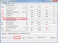
Hi David, it looks like some sort of bug has crept into the latest version of Hornresp. When I import a BOXPLAN sim, the "Edit" button is no longer enabled, allowing the user to select the "Loudspeaker Wizard" feature and then use F6 to update the imported sim.
still I would like to hear your thoughts on the subject.
Not sure what else to say. The obvious bottom line is that the closer the actual build matches the simulated design then the closer the measured results will be to the predictions.
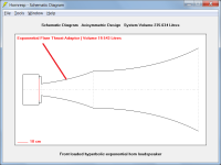
the possibility to simulate multisegment Hypex's and Exp-Hypex hybrids would be a worthy improvement
Exp-Hypex is already possible using an exponential throat adaptor, as shown in the attachment.
Multiple segment horns using flares other than Con, Exp or Par are not going to happen.
Attachments
Last edited:
the "Edit" button is no longer enabled
It never was!
The newly-imported record should be in edit mode, allowing the Loudspeaker Wizard to be selected from the Tools menu. Is this not the case?
It works just fine for me 🙂.
Attachments
I have been off the forum for a few weeks.Hmm... I have a design equation for 6th order parallel-tuned BP systems hidden somewhere in my archives ... 🙂
But, yes Sir, please!
Feature request - chamber(s) resonance display and markers
Hello David,
Couple of years ago, I requested that system fundamental frequency be highlighted in frequency response and impedance charts.
Now, with more experience and I try higher order designs. I find the system response to be highly non-linear to any change in parameters. The cause and effect are difficult to visualize.
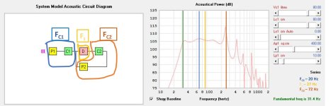
Please consider request to add a feature that marks and lists the fundamental frequencies of the sealed chambers/BR chambers/ TLs/horns/driver(s) in a particular design, along with the overall system fundamental frequency.
Regards,
Giri
Hello David,
Couple of years ago, I requested that system fundamental frequency be highlighted in frequency response and impedance charts.
Now, with more experience and I try higher order designs. I find the system response to be highly non-linear to any change in parameters. The cause and effect are difficult to visualize.
Please consider request to add a feature that marks and lists the fundamental frequencies of the sealed chambers/BR chambers/ TLs/horns/driver(s) in a particular design, along with the overall system fundamental frequency.
Regards,
Giri
Attachments
Hi all,
I'd like to check a BP4 simulation for port velocity and Xmax at different Pmax values, it seems it's not possible.
What alternativ enclosure(front loaded horn, closed rear chamber?) is suitable for that task to convert the BP4 to?
Thanks!
I'd like to check a BP4 simulation for port velocity and Xmax at different Pmax values, it seems it's not possible.
What alternativ enclosure(front loaded horn, closed rear chamber?) is suitable for that task to convert the BP4 to?
Thanks!
Hi @rertrobaer
Try:
Front loaded horn with closed back chamber.
Horn with min.3 segments.
Segment 1: chamber
Segment 2: transition to port (very short)
Segment 3: port
It makes sense to have all conical segments!
Try:
Front loaded horn with closed back chamber.
Horn with min.3 segments.
Segment 1: chamber
Segment 2: transition to port (very short)
Segment 3: port
It makes sense to have all conical segments!
Please consider request to add a feature that marks and lists the fundamental frequencies of the sealed chambers/BR chambers/ TLs/horns/driver(s) in a particular design, along with the overall system fundamental frequency.
The amount of work required to fully integrate the feature would be massive - it's not going to happen! 🙂
I'd like to check a BP4 simulation for port velocity and Xmax at different Pmax values, it seems it's not possible.
What alternativ enclosure(front loaded horn, closed rear chamber?) is suitable for that task to convert the BP4 to?
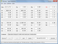
The method suggested by stv does not take into account the port tube internal end correction included in the BP4 model.
To make the results identical to those produced by the BP4 model, specify a closed mouth plus rear chamber and port tube as shown in the attachment, and use the chamber resonances 'Not masked' option. The ported chamber is defined using Vrc, Lrc, Ap and Lpt, and the sealed chamber is defined using S1 = S2 and L12 (Con) with Clo closed mouth .
Attachments
Segment 2: transition to port (very short)
A transition segment is not required if stepped segments are specified.
Not sure that I understand.
The Helmholtz resonance frequency of a bass reflex system is a function of the dimensions of the chamber and port tube, not of the driver voice coil dc resistance.
Using your record as a baseline, specifying two drivers in series or two drivers in parallel or changing Re to 3.08 ohms, all result in the same resonance frequency of 43.4 Hz.
Attachment 1 - Baseline record
Attachment 2 - Two drivers in series (Nd = 2S)
Attachment 3 - Two drivers in parallel (Nd = 2P)
Attachment 4 - Re = 3.08 ohms
The power responses of Attachments 2 and 3 have the same shape but different levels
Very late this time, thank you i think i finally understood.
The speaker Re changes if i wire a dual voice coil differently but not if i wire two different speakers differently ? (that would make sense)
BTW if you want to know, the difference was talking about wasn't the enclosure frequency tuning but the difference of chamber size i had to make for the same frequency response curve.
Now i'm on this forum again, i'd like to ask more questions:
This is the record:
And I'd like to know if I can do it this way (I imagine it has nothing to do with isobaric as there is no sealed chamber):
or maybe (longer Lc1&2 i imagine):
And in the fist picture, the Lc1 should be the space between (the center of) each woofer and the wall, right ?
(thank you and again maybe sorry for my english level)
The speaker Re changes if i wire a dual voice coil differently but not if i wire two different speakers differently ?
If the Re of each driver is 6 ohms, then two connected in series will have a combined resistance of 12 ohms and two connected in parallel will have a combined resistance of 3 ohms.
And I'd like to know if I can do it this way
I am not sure how to interpret your drawings. In any event I suspect that it is likely to be a judgement call, in which case your guess would be as good as mine.
Ok thanks. If i understood your answer correctly, i still haven't understood how it works.
I mean why does the curve shape change when we only change the Re of one speaker (2 to 8 in my case) and not when the Re changes with 2 speakers (2 to 8 when going from parallel to series, wich only changes the level) ?
Sorry for the continuous questioning but i have trouble to do things before understanding them.
And for my drawings i'd also like to know how to get the Lc number when the cabinet has a weird shape. I also wanted to know if we mount the speakers 180° (as an isobaric) would work like a normal dual driver vented chamber when ported (so not isobaric then) but that's off topic.
Thanks again. (for my series bandpass project i think i'll do a new topic as i still have a lot of questions anyway so i stop using this one too much)
Last edited:
I think I need some clarifications on the throat adaptor...
I managed to bring up the throat adaptor wizard by clicking on Ap1 text box, but I dont understand the meaning of the paramaters (what they refer to) Ap1, S1, Lp, Fta in the conical adapter and the whole list in the Exp adapter wizard.
Also no matter what values I input in the wizard, the adapter is not displayed, it is alway a 2 segments horn, not 2 segments + adapter.
- Home
- Loudspeakers
- Subwoofers
- Hornresp