the port tube is relatively long compared to the 30 Hz wavelength
Rule of thumb - needs to be less than one sixteenth of a wavelength at 30 Hz to be considered a pure acoustic mass.

Thank you so much for your reply and for taking the time to help me.I'll take a stab at it...
I suspect that the "standard" equation that you see for calculating Lv, given Dv, Vb and Vb assumes that Vb >>> Vp, where Vp is the volume of the port, which is Ap*Lp (a.k.a. "Lv" in the equations you quoted). In your case, Vp works out to be 49.5 liters (330*150/1000), which is almost the size of Vb, so the "standard" equation no longer gives valid results.
I further suspect that if you substitute (Vb+Vp) for Vb in the "standard" equation, you might get a much more accurate result, but that would of course require you knowing Lv beforehand in order to calculate a value for Lv 🙂. I guess it might be possible to rejig the equation to solve for Lv, but I suspect that the resulting equation would be pretty complex.
FWIW, it's because of a similar observation to yours that I long ago stopped using that "standard" equation for any design work involving vents.
I found a simple and very effective solution!I'll take a stab at it...
I suspect that the "standard" equation that you see for calculating Lv, given Dv, Vb and Vb assumes that Vb >>> Vp, where Vp is the volume of the port, which is Ap*Lp (a.k.a. "Lv" in the equations you quoted). In your case, Vp works out to be 49.5 liters (330*150/1000), which is almost the size of Vb, so the "standard" equation no longer gives valid results.
I further suspect that if you substitute (Vb+Vp) for Vb in the "standard" equation, you might get a much more accurate result, but that would of course require you knowing Lv beforehand in order to calculate a value for Lv 🙂. I guess it might be possible to rejig the equation to solve for Lv, but I suspect that the resulting equation would be pretty complex.
FWIW, it's because of a similar observation to yours that I long ago stopped using that "standard" equation for any design work involving vents.
I used the traditional formula and calculated Lv and Vb. I repeated the formula using the port volume (Vp) from the traditional formula along with a correction factor of 5.5. Now the result of the traditional formula is exactly the same for any situation of Vb and Lv.
I tested it in almost 50 different situations, varying Vb and Fb and Lv and obtained a maximum deviation of 1Hz for any simulation!!! 🙂
Hello everyone, I'm just starting out with using horn response and learning as I go.
I was just curious if anyone knows if it's possible to simulate a front loaded bass horn that has two passive radiators in the throat of the horn along with the driver itself, all sharing one sealed chamber?
Would I just need to follow the instructions for modeling a vented horn with the port exit inside the mouth of the horn, or is there another way to go about it?
Thank you all!
I was just curious if anyone knows if it's possible to simulate a front loaded bass horn that has two passive radiators in the throat of the horn along with the driver itself, all sharing one sealed chamber?
It cannot be done using Hornresp.
I found a simple and very effective solution!
I used the traditional formula and calculated Lv and Vb. I repeated the formula using the port volume (Vp) from the traditional formula along with a correction factor of 5.5. Now the result of the traditional formula is exactly the same for any situation of Vb and Lv.
I tested it in almost 50 different situations, varying Vb and Fb and Lv and obtained a maximum deviation of 1Hz for any simulation!!!
Just a note of caution - fudging formulas is fraught with danger.
When you say that you tested almost 50 different situations, what is it that you did exactly, and what are you trying to achieve?
If you simply want to design a bass reflex loudspeaker using a given driver, then possibly the safest way to go about it is to iterate the design in the Hornresp loudspeaker wizard until you obtain the response that you want. The problem with relying on a single formula is that it will be based on assumptions that may not necessarily apply to the specific design being considered, as I tried to explain in my earlier post.
The three formulas you showed originally will produce a valid design only if the calculated length of the port tube proves to be less than about c / (fb * 16).
Even the "c/(Fb*16)" limit might be a bit optimistic.
With my "Enigma" 4th order BP build I did years ago, the calculated length of each vent was within the "c/(Fb*16)" limit and they still turned out to be too long to hit the target Fb, which ended up being closer to 48 Hz instead of 58 Hz. I had to trim the vents down a bit to get close to the target Fb, and when I rebuilt the subwoofer after I got it back from Dad's place, I ended up trimming the vents even further to try and flatten the passband. I ended up with vents somewhere between 66%~75% of their original length, and I'm pretty sure a bit more could have been trimmed from them. I think my build was hit with the double-whammy of vents being too long and the discrepancies caused by the use of the lumped-mass model for 4th order BP designs that I pointed out in an earlier message.
With my "Enigma" 4th order BP build I did years ago, the calculated length of each vent was within the "c/(Fb*16)" limit and they still turned out to be too long to hit the target Fb, which ended up being closer to 48 Hz instead of 58 Hz. I had to trim the vents down a bit to get close to the target Fb, and when I rebuilt the subwoofer after I got it back from Dad's place, I ended up trimming the vents even further to try and flatten the passband. I ended up with vents somewhere between 66%~75% of their original length, and I'm pretty sure a bit more could have been trimmed from them. I think my build was hit with the double-whammy of vents being too long and the discrepancies caused by the use of the lumped-mass model for 4th order BP designs that I pointed out in an earlier message.
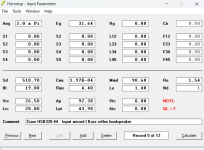
Wow, i'm late, sorry. Here's a Ciare HSB320 44 in a 30l BR box tuned to F1 note with the max power my amp would give mePlease post a copy of the record you are using, so that I can investigate further.
(i'll use a DSP to make it correct up to 250hz)
The result seems a bit powerful.
If i put RE to 3,08 (what would happen with one amp per voice coil if i understood correctly), i need a bigger box to get the same tuning. The excursion is also longer with the same (W) power.
But when i put 2 drivers in parallel in the loudspeaker configuration window, the result doesn't change compared to the same 2 drivers in serie. This is why i think there is something i'm wrong.
Attachments
Yup! One quick check to remove some of that danger is to check the dimensions in the formula.Just a note of caution - fudging formulas is fraught with danger.
For example, if the formula is supposed to produce a parameter with a length dimension (e.g. "cm") then the dimensions of each parameter in the formula should reduce to that dimension.
e.g. ...
1. X (given in cm) = A (given in cm) + B (given in cm) *C (a constant), that formula may work. The formula is dimensionally sound.
However,
2. X (cm) = A (cm) * B (cm) * C is NOT going to work, because the A*B calculation results in a parameter with dimensions given in cm*cm = cm^2. The formula is dimensionally unsound.
Thank you for the response. Do you know if there is another program that can simulate this type of enclosure?It cannot be done using Hornresp.
I'm thinking there's is probably one or more fundamental reasons I'm not aware of that explain why I can't seem to find a lot of info around for this idea...
Which edition of the LDC, btw?[snip]
BP4 band pass loudspeaker dimensions can now be automatically calculated for a given passband ripple and sensitivity by selecting the Other input option in the Loudspeaker Wizard, double-clicking the Auto Off label and specifying the desired ripple magnitude and sensitivity. The method used is documented in the Vance Dickason Loudspeaker Design Cookbook.
[snip]
I've got the old 5th edition, and I think Dickason used lookup tables where simple equations could have sufficed.
For example, he used tables for different values of "S", relating Qbp to sensitivity (which should really be "Gain" IMO, not "Sensitivity").
Qbp however can be calculated from S and the chosen Gain using the equation Qbp=((10^(-Gain/40))*2*S)^-1, so there's no need for a lookup table. This also opens up the possibility of using any value for S, rather than the 0.7, 0.6 and 0.5 given in the LDC.
I still haven't figured out why there's some sort of discrepancy with the calculation of the rear volume though. The Hornresp FR for the sim built using the 4th order design info from the LDC suggests that Vr is undersized, and after running several sims it's almost like you've got to subtract 2.5 dB from the chosen gain, and then use that new figure, let's call it "Gain1", in the calculations for Qbp and then use that new value for Qbp to calculate Vr.
If i put RE to 3,08 i need a bigger box to get the same tuning.
But when i put 2 drivers in parallel in the loudspeaker configuration window, the result doesn't change compared to the same 2 drivers in serie.
Not sure that I understand.
The Helmholtz resonance frequency of a bass reflex system is a function of the dimensions of the chamber and port tube, not of the driver voice coil dc resistance.
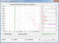
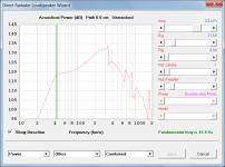
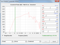
Using your record as a baseline, specifying two drivers in series or two drivers in parallel or changing Re to 3.08 ohms, all result in the same resonance frequency of 43.4 Hz.
Attachment 1 - Baseline record
Attachment 2 - Two drivers in series (Nd = 2S)
Attachment 3 - Two drivers in parallel (Nd = 2P)
Attachment 4 - Re = 3.08 ohms
The power responses of Attachments 2 and 3 have the same shape but different levels
Attachments

One quick check to remove some of that danger is to check the dimensions in the formula.
A very useful "sanity check" tip given to me almost a lifetime ago by my first physics teacher... 🙂.
Thanks for posting it here.
Do you know if there is another program that can simulate this type of enclosure?
AKABAK: http://www.randteam.de/AKABAK3/
I'm thinking there's is probably one or more fundamental reasons I'm not aware of that explain why I can't seem to find a lot of info around for this idea...
I suspect that there must be a very good reason 🙂.
Hi Brian,
I have a copy of the seventh edition of the Loudspeaker Design Cookbook.
I wondered about that from the very beginning. Sensistivity will be changed to Gain in the next update.
Excellent, many thanks for making me aware of the formula. I have checked it against the Qbp values in the tables and they all match exactly, except for the 4 dB sensitivity/gain entry in the S = 0.7 table (Table 1.25 in my edition). The formula calculates 0.8992 but the table shows 0.8772. It's obviously a typo in the table.
The formula will replace the three lookup tables in the next update.
It also opens up the possibility of increasing the Gain range, but the existing -8 dB to 8 dB is probably wide enough already.
Do you happen to know the relationship between the value of S and the ripple magnitude?
Given datapoints:
S = 0.7 Ripple = 0.00 dB
S = 0.6 Ripple = 0.35 dB
S = 0.5 Ripple = 1.25 dB
If you do, could you please let me know 🙂.
Kind regards,
David
Which edition of the LDC, btw?
I have a copy of the seventh edition of the Loudspeaker Design Cookbook.
which should really be "Gain" IMO, not "Sensitivity"
I wondered about that from the very beginning. Sensistivity will be changed to Gain in the next update.
Qbp however can be calculated from S and the chosen Gain using the equation Qbp=((10^(-Gain/40))*2*S)^-1
Excellent, many thanks for making me aware of the formula. I have checked it against the Qbp values in the tables and they all match exactly, except for the 4 dB sensitivity/gain entry in the S = 0.7 table (Table 1.25 in my edition). The formula calculates 0.8992 but the table shows 0.8772. It's obviously a typo in the table.
so there's no need for a lookup table.
The formula will replace the three lookup tables in the next update.
This also opens up the possibility of using any value for S, rather than the 0.7, 0.6 and 0.5 given in the LDC.
It also opens up the possibility of increasing the Gain range, but the existing -8 dB to 8 dB is probably wide enough already.
Do you happen to know the relationship between the value of S and the ripple magnitude?
Given datapoints:
S = 0.7 Ripple = 0.00 dB
S = 0.6 Ripple = 0.35 dB
S = 0.5 Ripple = 1.25 dB
I still haven't figured out why there's some sort of discrepancy with the calculation of the rear volume though.
If you do, could you please let me know 🙂.
Kind regards,
David
I tested it exactly like this:Just a note of caution - fudging formulas is fraught with danger.
When you say that you tested almost 50 different situations, what is it that you did exactly, and what are you trying to achieve?
If you simply want to design a bass reflex loudspeaker using a given driver, then possibly the safest way to go about it is to iterate the design in the Hornresp loudspeaker wizard until you obtain the response that you want. The problem with relying on a single formula is that it will be based on assumptions that may not necessarily apply to the specific design being considered, as I tried to explain in my earlier post.
The three formulas you showed originally will produce a valid design only if the calculated length of the port tube proves to be less than about c / (fb * 16).
10 boxes with fb=30Hz varying Vb from 10 liters to 100 liters.
10 boxes with Vb = 30 liters varying Fb from 20Hz to 100Hz
10 boxes with Vb = 60 liters varying Fb from 20 to 100Hz.
10 boxes with Vb = 100 liters varying Fb from 20 to 100Hz.
10 boxes with 300 liters varying Fb from 20 to 100Hz.
total = 50 different situations.
I humbly ask you to test the formula I passed in these conditions and then give me an answer, if you think it's convenient..
I tested it exactly like this:Even the "c/(Fb*16)" limit might be a bit optimistic.
With my "Enigma" 4th order BP build I did years ago, the calculated length of each vent was within the "c/(Fb*16)" limit and they still turned out to be too long to hit the target Fb, which ended up being closer to 48 Hz instead of 58 Hz. I had to trim the vents down a bit to get close to the target Fb, and when I rebuilt the subwoofer after I got it back from Dad's place, I ended up trimming the vents even further to try and flatten the passband. I ended up with vents somewhere between 66%~75% of their original length, and I'm pretty sure a bit more could have been trimmed from them. I think my build was hit with the double-whammy of vents being too long and the discrepancies caused by the use of the lumped-mass model for 4th order BP designs that I pointed out in an earlier message.
10 boxes with fb=30Hz varying Vb from 10 liters to 100 liters.
10 boxes with Vb = 30 liters varying Fb from 20Hz to 100Hz
10 boxes with Vb = 60 liters varying Fb from 20 to 100Hz.
10 boxes with Vb = 100 liters varying Fb from 20 to 100Hz.
10 boxes with 300 liters varying Fb from 20 to 100Hz.
total = 50 different situations.
I humbly ask you to test the formula I passed in these conditions and then give me an answer, if you think it's convenient..
Exactly!Yup! One quick check to remove some of that danger is to check the dimensions in the formula.
For example, if the formula is supposed to produce a parameter with a length dimension (e.g. "cm") then the dimensions of each parameter in the formula should reduce to that dimension.
e.g. ...
1. X (given in cm) = A (given in cm) + B (given in cm) *C (a constant), that formula may work. The formula is dimensionally sound.
However,
2. X (cm) = A (cm) * B (cm) * C is NOT going to work, because the A*B calculation results in a parameter with dimensions given in cm*cm = cm^2. The formula is dimensionally unsound.
I humbly ask you to test the formula I passed in these conditions and then give me an answer, if you think it's convenient..
What value was used for R, the bass reflex tube diameter in inches?
Was the same R value used for all tests?
Just one test...
Given:
Vb =100 litres
fb = 50 Hz
Ap = 25 cm^2 (port cross-sectional area assumed for the purposes of the test)
Vb = 6102.37 inches^3
R = 2.22 inches
Lv = 1.39 inches
Vp = 5.40 inches^3
Lpt = 1.48 inches = 3.75 cm
Using the values of Vb, Ap and Lpt (in cm) as inputs, Hornresp calculates the resonance frequency to be 30.8 Hz when the design frequency is 50 Hz.
- Home
- Loudspeakers
- Subwoofers
- Hornresp