But when i set 2 drivers in parallel or in serie, the simulation doesn't change at all.
Please post a copy of the record you are using, so that I can investigate further.

Hello all,
I have some general questions regarding Hornresp:
1.) Under Acoustical power it seems to only be possible to look at the directivity tools for horns that are single segment. It's grayed out for multi segment horn.
Is that true that it is not possible to analyse directivity for multi segment horns or am I missing something?
2.) When using the Loudspeaker Wizard to add filler material for a transmission line or similar, I can see the response change and I save the result. But then when I press calculate I can't see the effect of filler material in the Acoustic Power plot anymore. Is there an option that I can set to be able to see what the filler material is doing for all calculations in my record?
In the Loudspeaker Wizard it doesn't seem possible to Capture results and compare different records with and without filler material?
3.) How do I simulate filler material lining the walls of a horn or transmission line? Do I need to recalculate the material porosity or absorption to make an equivalent plug of absorber material or is there another way to do it properly?
4.) Is it possible to calculate a multi segment horn from driver parameters the same way as can be done for a single section?
5.) Is it possible to do a multisegment horn with Le Cléac'h, Tractrix or any type of flare? How do I go about doing that?
6.) Is the helpfile available as PDF somewhere, scrolling with the mouse wheel does not seem to work for me. Is there an illustrated manual somewhere that has more pictures and some deeper explanations than the helpfile?
It's true.Is that true that it is not possible to analyse directivity for multi segment horns or am I missing something?
No.Is there an option that I can set to be able to see what the filler material is doing for all calculations in my record?
Correct. Only the current record in the Wizard can be compared with and without absorbent filling material.In the Loudspeaker Wizard it doesn't seem possible to Capture results and compare different records with and without filler material?
There is no other way.How do I simulate filler material lining the walls of a horn or transmission line? Do I need to recalculate the material porosity or absorption to make an equivalent plug of absorber material or is there another way to do it properly?
No. The TL Design tool can be used for a transmission line loudspeaker however.Is it possible to calculate a multi segment horn from driver parameters the same way as can be done for a single section?
No. Only with conical, exponential and parabolic flares.Is it possible to do a multisegment horn with Le Cléac'h, Tractrix or any type of flare?
The Help file can be exported and converted to a PDF file externally, as done above by Mark.Is the helpfile available as PDF somewhere, scrolling with the mouse wheel does not seem to work for me. Is there an illustrated manual somewhere that has more pictures and some deeper explanations than the helpfile?
There is a vertical scroll bar on the right hand side of the Help file window.
Manual: https://dokumen.pub/qdownload/hornresp-manual.html
Is it going to happen to calculate a BP6 in HR? That would be awesome! If i got it right a BP4 is a sealed box+LPF and a BP6 is a vented box+LPF, it's probably not that easy, but maybe in the calculation for BP4 the sealed-box-part just needs to be replaced by a formula for a vented-box?Hmm... I have a design equation for 6th order parallel-tuned BP systems hidden somewhere in my archives ... 🙂
Hornresp has wizards for parallel and serial BP6 and BP8. If you just want to add a LPF to a vented box use the filter wizard after calculation.
By the way: parallel BP6 can becalculated (edit) simulated using a vented chamber horn! Serial is probably also possible (using tapped horn?).
By the way: parallel BP6 can be
Last edited:
By vented-box+LPF i mean an acoustic LPF, as this is my understanding of the principle of a (parallel)BP6. My question was pointing at
, if this might also happen for BP6 in Hornresp, that would be great.CHANGE
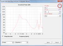
BP4 band pass loudspeaker dimensions can now be automatically calculated for a given passband ripple and sensitivity
In general, one could make a band pass with anything.
Like some kind of TL or horn on the back and just a port on the front.
Vice versa is technically also possible, although I don't see many benefits with that.
Or use passive radiators as well (or a combination of all)
Like some kind of TL or horn on the back and just a port on the front.
Vice versa is technically also possible, although I don't see many benefits with that.
Or use passive radiators as well (or a combination of all)
Does anyone have a good methodology for designing multi-segment horns?
My design goals are:
1.) High effeciency, or rather maximum SPL output
2.) Even and controlled directivety in two (or more directions. If the horn is placed high up the lower directivity could be narrower while the upper part could be wider) directions.
3.) Minimum reflection effect causing standing waves an "bad horn sound"
The target design is for small PA use of point source speaker/speakers
From what I gathered this means that I need:
1.) Well matched and terminated throat and mouth impedance's to reduce reflections
2.) A large conical section of the horn to control directivity
3.) A different wider flare after the conical section to reduce diffraction and make a smoother mouth termination
4.) either an exponential section close to the throat to give good loading or alternatively a conical section to quickly spread high frequencies at the begining of the horn to avoid beaming
5.) Possibly a diffraction slot to spread high frequencies.
I realize that this is what horn design is all about and that there is not one answer how to do this.
But what i'm looking for is some advice on how you would approach a design like this?
Would you first design a single section and get an idea about the general length and mouth size and then start braking it down into sections?
What goals would you start with?
In some cases the automatic bp4 calculator creates negative volume.
Hi rertrobaer,
Thanks for the feedback.
The formula used in the Vance Dickason method to calculate the volume of the rear unported chamber is:
Vr = Vas / ((Qbp / Qts) ^ 2 - 1)
Where:
Vr = Rear chamber volume
Vas = Volume of air that provides a restoring force equal to the driver's mechanical compliance
Qbp = Q of bandpass rear chamber
Qts = Driver total Q
In your example, for a ripple of 0.35 dB and a sensitivity of 0 dB, Table 1.26 in the Vance Dickason Cookbook gives Qbp as 0.8333.
The value of Vas for the driver you have specified is 0.90 litres, and the value of Qts is 1.035 (shown rounded to 1.04 in Hornresp).
This means that:
Vr = 0.90 / ((0.8333 / 1.035) ^ 2 - 1) = -2.56 litres
In other words, if Qts is greater than Qbp then the calculated value of Vr will be negative.
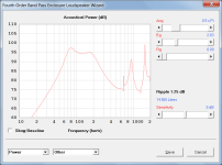
Interestingly, simply changing the calculated value from negative to positive seems to produce reasonable results, as shown in the attachments. To prevent invalid values from occurring, as from the next update the absolute value (in this case 2.56 litres) will be used instead for Vr.
Kind regards,
David
Attachments
Last edited:
Hi David!Hi Everyone,
Just letting you know that Hornresp Version 18.00 has now been released.
The Tapped Horn Wizard tool has been significantly enhanced. For a given overall horn length, flare rate and driver specification, the optimum driver position can be determined more easily than before.
Note that there are three ‘Interaction’ options. The operation of the first two should be pretty obvious from the titles. The third ‘L12 & L34 Linked’ setting enables the user to “slide” the driver along the mounting baffle / separating panel towards or away from the 180 degree bend (similar to changing the acoustic path length of a slide trombone).
Hopefully the Tapped Horn Wizard is now a far more useful tool. Enjoy 🙂.
Kind regards,
David
How are you? All good? I used HornResp software and it is amazing! Congratulations!
I'm a bass enthusiast and using your software I came across a question that I'm not able to solve. Let's say I have the following subwoofer:
| Fs | 77,6 | Hz |
| Vas | 0,380 | ft^3 |
| Vas | 10,75 | liters |
| Qms | 8,29 | |
| Qes | 0,454 | |
| Qts | 0,43 | |
| Sensib | 92,67 | |
| No | 1,06 | % |
| Power | 4500 | W rms |
| Xmax | 11 | mm |
| Sd | 0,05272 | m^2 |
| Vd | 0,58 | liters |
| Impedance | 4 | Ohms |
| Bl | 20,38 | T*m |
| Diameter | 12 | inches |
| Cone Diameter | 10,32 | inches |
| Sub Displacement | 3 | liters |
| Le | 1,25 | mili Henries |
| QL | 15 | |
| Re | 2,5 | Ohms |
Using your HornResp with a 50 liters box and a port with 330cm^2 of area and using L=150cm (length of port) I see a Fb=30Hz.
Using the same subwoofer and same box parameters with 3 other softwares I have a port with L=210cm. 60cm of difference! All 3 softwares showing L=210cm and HornResp showing L=150cm. So... I decided to make the enclosure and measure it.
And what was the result? Really with the duct L=150cm the box was even tuned to 30Hz!!! HornResp won! But my curiosity went further. I've read some technical articles about ports and the general formula to calculate is (generally) one of 3 below:
Where:
I try all formulas and get the same result of the wrong softwares. Never the same result of HornResp. My question: What am I doing wrong? Or rather, what would be the error of the other 3 softwares? Could you explain to me, please? HornResp uses a different formula?
Last edited:
The formula used in the Vance Dickason method to calculate the volume of the rear unported chamber is:
Vr = Vas / ((Qbp / Qts) ^ 2 - 1)
Where:
Vr = Rear chamber volume
Vas = Volume of air that provides a restoring force equal to the driver's mechanical compliance
Qbp = Q of bandpass rear chamber
Qts = Driver total Q
[snip]
In other words, if Qts is greater than Qbp then the calculated value of Vr will be negative.
What happens if Qbp = Qts? 🙂
I'll take a stab at it...I try all formulas and get the same result of the wrong softwares. Never the same result of HornResp. My question: What am I doing wrong? Or rather, what would be the error of the other 3 softwares? Could you explain to me, please? HornResp uses a different formula?
I suspect that the "standard" equation that you see for calculating Lv, given Dv, Vb and Vb assumes that Vb >>> Vp, where Vp is the volume of the port, which is Ap*Lp (a.k.a. "Lv" in the equations you quoted). In your case, Vp works out to be 49.5 liters (330*150/1000), which is almost the size of Vb, so the "standard" equation no longer gives valid results.
I further suspect that if you substitute (Vb+Vp) for Vb in the "standard" equation, you might get a much more accurate result, but that would of course require you knowing Lv beforehand in order to calculate a value for Lv 🙂. I guess it might be possible to rejig the equation to solve for Lv, but I suspect that the resulting equation would be pretty complex.
FWIW, it's because of a similar observation to yours that I long ago stopped using that "standard" equation for any design work involving vents.
LOL...The world will explode! 😀 😉
David, I think it might be better to just put in an error check for the calculation. e.g. Qbp cannot be set to a value that's less than 1.1*Qts. As Qbp approaches Qts, the calculated value for Vr will be HUGE, so best just to avoid that happening altogether by putting a hard upper limit its value.
Just in case anyone's interested, I believe the equations from the LDC to calculate 4th order BP systems assume zero losses. I've got a couple of equations that calculate frequency response for bandpass alignments (using lumped-mass modeling) and they basically give identical results for bandwidth and F3 points when Fr and box losses are set to zero (Fr being the vent resonance frequency for the rear chamber, and 4th order BP systems don't have vented rear chambers). Hornresp seems to assume zero box losses as well, so the FR shown by the Hornresp sim should be pretty close if not identical to what's predicted by my equations. Hmm, maybe it's time for a test sim to find out... 🙂
Here's a quick comparison - my old BANDPASS.XLS workbook uses lumped-mass modeling. Results are basically identical to what the equations from the LDC predict. However, the Hornresp sim's calculated response suggests that Fb is set a bit low, or something else is off. Hmm....
Yes, I know the volumes are slightly different between the two sims, but the differences are minor and have little effect on the frequency response.
Based on some experience I've had with some bandpass builds, I suspect that the Hornresp sim might actually be more accurate.

Yes, I know the volumes are slightly different between the two sims, but the differences are minor and have little effect on the frequency response.
Based on some experience I've had with some bandpass builds, I suspect that the Hornresp sim might actually be more accurate.
Here's a comparison of the predicted FRs. I aligned them along the slope at lower frequencies.
While the lumped-mass model produces results that matches the info in the LDC (i.e. gain, F3h and F3l), it's been my experience that the wider passband predicted by the Hornresp (and the non-flat response that's a bit biased towards lower frequencies) is the result of building a 4th order BP alignment using the LDC information.

Here I modified Fb in the Hornresp sim to flatten the passband. The sim's passband is still wider than that predicted by the lumped-mass model.

...and here I modified Vr (i.e. made it larger) in the Hornresp sim to flatten the passband. Again, the sim's passband is wider than that predicted by the lumped-mass model.

Finally here I shifted the FR for the "modified Vr" sim down by 3.8 dB. Now the slopes line up.

Again, based on the experience I had with two builds (see http://www.diysubwoofers.org/projects/home/inf10bp/ for example), I think the Hornresp sim is the more accurate of the two, and if that's correct, the LDC method may need to be modified, or it should just be considered as a starting point, with some subsequent adjustment required after running the wizard.
While the lumped-mass model produces results that matches the info in the LDC (i.e. gain, F3h and F3l), it's been my experience that the wider passband predicted by the Hornresp (and the non-flat response that's a bit biased towards lower frequencies) is the result of building a 4th order BP alignment using the LDC information.
Here I modified Fb in the Hornresp sim to flatten the passband. The sim's passband is still wider than that predicted by the lumped-mass model.
...and here I modified Vr (i.e. made it larger) in the Hornresp sim to flatten the passband. Again, the sim's passband is wider than that predicted by the lumped-mass model.
Finally here I shifted the FR for the "modified Vr" sim down by 3.8 dB. Now the slopes line up.
Again, based on the experience I had with two builds (see http://www.diysubwoofers.org/projects/home/inf10bp/ for example), I think the Hornresp sim is the more accurate of the two, and if that's correct, the LDC method may need to be modified, or it should just be considered as a starting point, with some subsequent adjustment required after running the wizard.
Last edited:
what would be the error of the other 3 softwares?
The three software packages you refer to all assume that the port tube is a pure acoustic mass (short enough so that the air in it moves as a whole without appreciable compression). The traditional Helmholtz resonator formulas are then used to arrive at a resonance frequency of 30 Hz given a port tube length of 210 cm. The simulation model used in the packages is not really valid for your example because the port tube is relatively long compared to the 30 Hz wavelength, and is therefore not acting as a pure acoustic mass.
Hornresp analyses the complete acoustic circuit of the system and treats the port tube as a cylindrical acoustic 'transmission line' rather than as just an acoustic mass, which is why the calculated system resonance frequency is different to that predicted by the other programs.
I think it might be better to just put in an error check for the calculation.
Agreed.
Hornresp will test for Qbp < 1.1 * Qts and display an error message.
For example, if the value of Qbp causing the error is 0.8333, then the message would read:
"Driver Qts must be less than 0.76."
(0.8333 / 1.1 rounded to two decimal places = 0.76)
- Home
- Loudspeakers
- Subwoofers
- Hornresp