Maybe the MEH Wizard can be abused for that?
https://www.diyaudio.com/community/threads/hornresp.119854/post-6535372

Hornresp Update 5460-230728
Hi Everyone,
A few minor loose ends noticed recently have now been "tied up".
Kind regards,
David
Hi Everyone,
A few minor loose ends noticed recently have now been "tied up".
Kind regards,
David
Hi woodo,
There are no new or enhanced features, visible or hidden. Some small sections of the source code have been tidied up, and refinements made to the Help File wording, but none of the changes affect the operation of the program in any way.
Kind regards,
David
There are no new or enhanced features, visible or hidden. Some small sections of the source code have been tidied up, and refinements made to the Help File wording, but none of the changes affect the operation of the program in any way.
Kind regards,
David
Hello David,
Are there any rules of thumb that exist for arriving at a good first guess design for band pass designs? Hornresp has this ability built in for transmission lines, based on MKJ and Brian Steele's algorithms. I'm referring to something similar.
Are there any rules of thumb that exist for arriving at a good first guess design for band pass designs? Hornresp has this ability built in for transmission lines, based on MKJ and Brian Steele's algorithms. I'm referring to something similar.
Hi Giri,
The Vance Dickason Loudspeaker Design Cookbook documents a method for calculating the dimensions of a BP4 band pass loudspeaker. I do not know if methods also exist for other more advanced band pass configurations.
When I get chance I will have a look at the Vance Dickason BP4 method to see if it could perhaps be integrated into Hornresp in some way.
Kind regards,
David
Realize what a BP design does, a part of it is already in the name.Hello David,
Are there any rules of thumb that exist for arriving at a good first guess design for band pass designs? Hornresp has this ability built in for transmission lines, based on MKJ and Brian Steele's algorithms. I'm referring to something similar.
It's just an acoustic lowpass filter in front of your loudspeaker design.
So a good way to start is just by taking the same design for a closed box (BP4) or a BR-design (BP6) and go, tweak and optimize from there.
When an active filter can be used, there aren't many advantages for a BP design left anymore.
Bandpass systems tend to redistribute energy, in a way. The sensitivity within the pass band is higher.Realize what a BP design does, a part of it is already in the name.
It's just an acoustic lowpass filter in front of your loudspeaker design.
So a good way to start is just by taking the same design for a closed box (BP4) or a BR-design (BP6) and go, tweak and optimize from there.
When an active filter can be used, there aren't many advantages for a BP design left anymore.
That totally depends how you tune them.Bandpass systems tend to redistribute energy, in a way. The sensitivity within the pass band is higher.
You can optimize them for higher sensitivity at the cost of having a (very) small frequency band.
This only works well for a BP6 btw.
Again one question which is not strictly horn-resp related.
I've been taught that in the far field, any loudspeaker has a round propagation wave. On the other side I keep reading that unlike direct radiation speakers (or other types of horns), only multicellar horns have a round propagation wave.
I assume this apparent contrast between the two notions, may have to do with the different propagation of arrays vs point source, and WHERE the transition between far field and near field actually happens with different types of loudspeakers, in relation to the actual radiating surface and shape, which is quite different in arrays and particularly in multicellulars when compared to the rest.
My assumption may well be wrong so hopefully someone will shed some light on the subject and clarify the matter.
I must confess I haven't investigated the transition between near field and far field radiation much, but there will be a difference between different types of radiators. In the near field, there will be different distances from different parts of the radiator to the observation point: on the axis of a piston the distance to the edge is larger than the distance to the center, and as you move off-axis, this changes. Since the pressure at the observation point is the sum of all the contributions from the elemental areas of the piston, there will be an interference pattern, depending on the differences in distance, in terms of wavelengths.
Moving further away, the geometry dictates that the difference in distances becomes smaller, and at some point the distance is such a small part of a wavelength that it can be ignored. We are now in the far field. Since this distance depends on the wavelength, the extent of the near field is frequency dependent, and of course also depends on the size of the radiator, and also on the shape of the wave front it emits.
Direct radiators and some horns radiate wave fronts that are not very spherical, so it may take some distance for the wave to become truly spherical. But most axisymmetrical constant directivity horns, and multicell horns, typically have a fairly spherical wave front to start with, so one may assume that the near field starts at a point closer to the horn than for devices where the starting wave front is flatter. Diffraction horns will have different curvature in the two planes, so they cannot establish a spherical wave in the near field, and probably require a fairly large distance before the wave becomes spherical.
Not having looked at this in detail, some of this is educated guesses. But at a sufficiently large distance, all radiators will behave essentially as point sources with directivity, producing spherical waves.
(I can also mention that when tractrix horns were becoming popular, it was claimed that they were the only horns that produced spherical waves. This statement was based on the geometry used in designing the profile, and had no basis in actual acoustics. It may be the same with multicell horns, since they are designed to produce a spherical wave front (or section of a sphere, actually). And we have not even considered diffraction effects. Be suspicious of statements like "only this type X horn (which I like/use/sell) produces type Y wave front, which I consider to be the optimum".)
When I get chance I will have a look at the Vance Dickason BP4 method to see if it could perhaps be integrated into Hornresp in some way.
It will be in the next update.
When an active filter can be used, there aren't many advantages for a BP design left anymore.
There is less cone movement and therfore lower distortion in a BP.
That also heavily depends on the tuning of the BP.There is less cone movement and therfore lower distortion in a BP.
But cone excursion in an active system will be limited by the active low pass filter.
In some cases people don't put a (1st order) low pass on a BP.
Which means that the woofer will get full electrical power above the acoustic low pass.
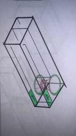
The 4th order BP limits excursion in-band. Also, the vent acts as a distortion filter (and from one of my measurements, it's pretty good at that - I've attached the distortion curves for one of my builds - not that this was taken at 70W input - the rated RMS of the driver used in this build. Note that the peak in the THD between 100 Hz to 200 Hz was caused by a loose x-over board in the enclosure, which I subsequently fixed.

That the woofer is getting full electrical power above the acoustic low pass is usually a non-issue as the woofer is concerned as most of the power in music is at bass frequencies, and the woofer's impedance is rising at this point anyway. It's actually more of a concern if designing a passive x-over to use the BP as part of a full range system, but even then, that's usually a minor concern.
I probably wouldn't use a 1st order passive LPF on a BP, unless I really had to.
That is correct! 🙂Also, the vent acts as a distortion filter (and from one of my measurements, it's pretty good at that
One of the benefits of acoustic lowpass filters!!
(there are also drawbacks)
Well yeah, true, my point was that it just all depends on the system design one is looking for.That the woofer is getting full electrical power above the acoustic low pass is usually a non-issue as the woofer is concerned as most of the power in music is at bass frequencies, and the woofer's impedance is rising at this point anyway. It's actually more of a concern if designing a passive x-over to use the BP as part of a full range system, but even then, that's usually a minor concern.
So it is important to know and adres these things 🙂
Btw, it might not be an issue for the woofer, it means that the amplifier still has to deliver the power.
So getting warmer/hotter in the end of the day. It's just power being wasted.
I usually add a simpel (passive) filter around roughly 200Hz
That way you limit the power somewhat as well as getting rid of some nasty (port) resonances you can get sometimes.
With a 4th order BP you have to be very careful not to push the driver over its xmax below the tuning fs dip (roughly around 0.85*tuning fs).
Since active filtering and amplifiers are so easy and cheap these days, you won't win much in practical sense.
Often the total volume of a BP will be similar as just a regular BR system.
Or in more affordable systems, the price of the additional construction will be similar as a second woofer in a closed system.
Last edited:
If I was going for a passive filter for a BP system, I'd probably aim to do it as far from the passband as possible, e.g. 2nd order or higher where the first out of band resonance starts to emerge.
The resonances themselves can be controlled a bit by modeling the design as an offset driver two-stage sealed horn, and use the driver location and "vent" (the second segment of the horn) to null out resonance modes. Hornresp can now model offset-driver / offset vent alignments, so that may provide even more accurate predictions, but I really haven't experimented with it yet. The 4th order BP that I provided the THD curve for has out of band resonances that are so low in level that it can be used without a passive x-over, but vents that are large enough to minimize any possible vent compression effects.
I seem remember KEF adding an internal vent to their 107 series which IMO was likely an attempt to reduce excursion requirements below the primary Fb. Basically they converted the design into a dual-driver tri-chamber series-tuned 6th order BP, but they didn't call it that 🙂 .
BP designs also provide one additional advantage - with the driver buried within the enclosure, it's a lot more difficult for it to suffer damage from the errant foot or child's fingers 🙂 .
Hornresp Update 5470-230805
Hi Everyone,
CHANGE
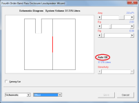
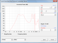
BP4 band pass loudspeaker dimensions can now be automatically calculated for a given passband ripple and sensitivity by selecting the Other input option in the Loudspeaker Wizard, double-clicking the Auto Off label and specifying the desired ripple magnitude and sensitivity. The method used is documented in the Vance Dickason Loudspeaker Design Cookbook.
Kind regards,
David
Hi Everyone,
CHANGE
BP4 band pass loudspeaker dimensions can now be automatically calculated for a given passband ripple and sensitivity by selecting the Other input option in the Loudspeaker Wizard, double-clicking the Auto Off label and specifying the desired ripple magnitude and sensitivity. The method used is documented in the Vance Dickason Loudspeaker Design Cookbook.
Kind regards,
David
Attachments
Hmm... I have a design equation for 6th order parallel-tuned BP systems hidden somewhere in my archives ... 🙂
Hello,
One question more. Simulating a box with a double voice coil change dramatically if i wire it in parallel or in serie (2ohms Z - 1,54ohms Re / 8ohms Z - 6,15ohms Re).
i can put much more power (W) with the parallel wiring without reaching xmax while having a significantly smaller box for the same frequencies, but of course with less sensitivity.
But when i set 2 drivers in parallel or in serie, the simulation doesn't change at all.
Is there something i missed ?
- Home
- Loudspeakers
- Subwoofers
- Hornresp