Is this possibly more of "The masters" work?
https://www.ebay.co.uk/itm/275075901848?hash=item400bcd2998:g:QJ4AAOSw32lYqdZW&LH_ItemCondition=10
https://www.ebay.co.uk/itm/275075901848?hash=item400bcd2998:g:QJ4AAOSw32lYqdZW&LH_ItemCondition=10
No.
Although it may look a little suspect if you are not familiar, that is very close to the original construction method, as well as being properly connected, grounded and fused.
Although it may look a little suspect if you are not familiar, that is very close to the original construction method, as well as being properly connected, grounded and fused.

Interesting, I recently repaired a similarly styled aleph j for a friend.
It had the standard challenges. No ground, bias was well out of whack and the fets were not matched.


It had the standard challenges. No ground, bias was well out of whack and the fets were not matched.
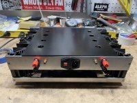
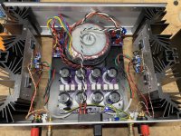
Just back from seeing The Cult. I still have some gas in the tank so I came down to my bench to crack open this amp.
Findings:
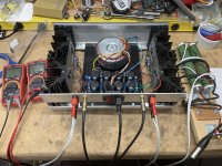
No earth ground. BAD
Single rectifier. OK
PSU is +/- 24.4V Good
Gain is 14dB. Good
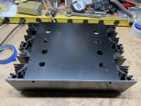
Proto board amp construction. OK
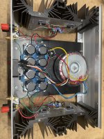
RCA grounds to amp boards are snipped and are now tied to Star. Curious
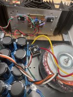
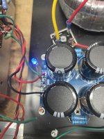
Psu appears to be dual CRC fed to center of board with 15kuf parallel 0R11 and then another 15kuf.
Donut wasn’t fully tight. Rotated it and used my headphone him tester. Null point on one channel still has residual hum on the other. And vice versa
Sound is nice on my crappy bench test speakers.
Primary complaint was hum.
My plan is to fix grounding (always first priority) and tackle hum. I’ll go for dual rectifiers with snubbers and tweak wiring. I’m likely going to put in a new PSU board.
Amp board plan for now is “ain’t broke, don’t fix it”.
Let’s see where this one goes.
Findings:
No earth ground. BAD
Single rectifier. OK
PSU is +/- 24.4V Good
Gain is 14dB. Good
Proto board amp construction. OK
RCA grounds to amp boards are snipped and are now tied to Star. Curious
Psu appears to be dual CRC fed to center of board with 15kuf parallel 0R11 and then another 15kuf.
Donut wasn’t fully tight. Rotated it and used my headphone him tester. Null point on one channel still has residual hum on the other. And vice versa
Sound is nice on my crappy bench test speakers.
Primary complaint was hum.
My plan is to fix grounding (always first priority) and tackle hum. I’ll go for dual rectifiers with snubbers and tweak wiring. I’m likely going to put in a new PSU board.
Amp board plan for now is “ain’t broke, don’t fix it”.
Let’s see where this one goes.
Attachments
Last edited:
It is an aleph j on a generic board. I think one of the major issues was a short between one of the resistors.

The bias across each fet was highly variable and when I pulled them, their vgs where nowhere near matched. Ended up using a new matched quad for each side.
I added a solid ground bus, xlr option for input and iec ground.
Overall build was pretty good though. Sounds good after the minor tweaks too.
Good luck with the F7
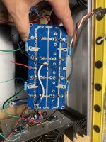
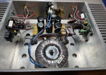
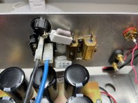
First pass, use original PSU, add snubbers, 2nd rectifier, fixed grounding. It was still humming a bit in my headphone hum tester.
Next up, swap to V8 CRCRC. I played around with wire dressing and went from a little hum to dead quiet.
Also I found a 10A fuse in the IEC. Changed it to a 2A.
Time to let it cook all night.
Next up, swap to V8 CRCRC. I played around with wire dressing and went from a little hum to dead quiet.
Also I found a 10A fuse in the IEC. Changed it to a 2A.
Time to let it cook all night.
Attachments
Great job!Proto board amp construction. OK
Have you seen Rawsons done on proto board before?
This is the first time I've seen amp boards on proto board. F7 is low parts count, so why not?
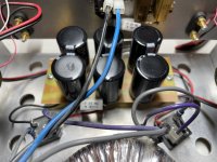
RCA grounds to amp boards are snipped and are now tied to Star. Curious
Psu appears to be dual CRC fed to center of board with 15kuf parallel 0R11 and then another 15kuf.
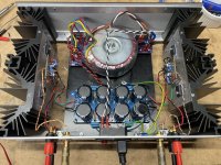
The ground star at the middle of the power supply board is in no man's land. The V+, V-, Gnd should enter the filter board at one end (dirty end) and exit at the other end (clean end). V+, V-, Gnd should be twisted together at entry and exit to minimize loop areas to minimize the wires from picking up noise.
The best place for a star ground is at the amplifier board. An audio star ground located on the amplifier board places the signal input, speaker output, and power supply grounds at exactly the same potential. It also minimizes loop areas as the input signal and input ground wires can be twisted together from RCA to amplifier board, the speaker signal and speaker ground wires can be twisted together from amplifier board to speaker jacks, and as mentioned the V+ V- G wires twisted together.
Some builders prefer taking the speaker ground from the power supply board. One problem with this is the speaker loop area then is large, inviting noise pickup, unless the ground wire is twisted with the power supply wires at the amplifier board back to the power supply board. Another issue is the wire between the power supply board ground and the amplifier board ground, as it can add resistance between the amplifier board ground and the power supply board ground.. So the amplifier circuit and input signal are at one ground potential and the speaker output is at a different ground potential.
Here is a very informative article by diyAudio member Bonsai:
Attachments
Adding another one to the list- an F3.
Notes when opening it up-
-No signal on the right channel.
-No CL-60 but a strange resistor set up to lower input voltage?
-No grounding, of course.
-54v from the power supply seems a bit too high.
The plastic spacers for the right channel RCA jack were either missing or melted and the input shorted. I replaced the jack, mounted it correctly and both channels worked.
I noticed that the back panel holding the resistor bundle got really hot, almost immediately. That bundle is right next to the right RCA jack. Hmm...that does not inspire confidence in playing the amp as it is. It looks like I'm off to the parts bin for a rummage and a call to rthatcher for advice and some new parts.
Next steps:
- Replace the power supply board with a new board, 63V caps, CL-60's and proper grounding.
- Replace the doughnut with an 36V one, giving me 43V at the amplifier boards.
- Remove the resistor bundle on the back panel.
Attachments
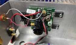
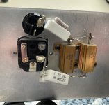
-No CL-60 but a strange resistor set up to lower input voltage?
extremely dangerous
whatever reason (excessive secondary voltage, so shaving it on primary side?), it can melt IEC, it can short to case .......
pull that out and decipher rail and what to do
Sweet baby jeezus, this is the most dangerous one yet.
😱
Please DO NOT ever turn this amp on again with its current AC wiring. That resistor pack is bare uninsulated AC and improperly grounded.
Unplug and start the restoration process by removing that gawd-awful resistor abomination sorting the AC wiring, and ordering a proper transformer.
😱
Please DO NOT ever turn this amp on again with its current AC wiring. That resistor pack is bare uninsulated AC and improperly grounded.
Unplug and start the restoration process by removing that gawd-awful resistor abomination sorting the AC wiring, and ordering a proper transformer.
Last edited:
Jim and ZM, I had a similar reaction!
This one is the first time I’ve seen this style of “creative” and dangerous wiring job on the mains.
I’m glad to see Will is prepared to fix this one up properly.
This one is the first time I’ve seen this style of “creative” and dangerous wiring job on the mains.
I’m glad to see Will is prepared to fix this one up properly.
- Home
- Amplifiers
- Pass Labs
- Rawson Repair Reflections