but how many parts are the minimum to make something sound good?
13 exactly

^
More parts
More transformers
More bias
More HEAT...
.
..13 parts... per channel... plus the power supply... plus the chassis... plus the cooling.... etc, etc... and then you need a 98db/watt speaker. I know, I know, details... I realized I should have added a condition in there... "how many parts do you need to drive a Magnepan?".

Back on topic. I have been corresponding privately with @Goggle1824 and I want to share some of the key points on that amp.
As far as I can tell, I think his amp is the first known case of the ground wire connecting from IEC Earth to chassis!!!
The amp uses DIYAudio store PCB's, dual donuts, and Gianluca's heatsinks. It is perhaps the nicest Rawson build I have seen to date.
The fuse in the unit was a 10A fast blow (default fuse that ships with some of the inexpensive IEC's). He will be installing proper fuses and then powering up.

^ Awesome! Seeing these amps safely and properly go back into service is a wonderful thing. 🙂
If it wasn't from the RRR oracle, I wouldn't have believed it.Back on topic. I have been corresponding privately with @Goggle1824 and I want to share some of the key points on that amp.
As far as I can tell, I think his amp is the first known case of the ground wire connecting from IEC Earth to chassis!!!
The amp uses DIYAudio store PCB's, dual donuts, and Gianluca's heatsinks. It is perhaps the nicest Rawson build I have seen to date.
The fuse in the unit was a 10A fast blow (default fuse that ships with some of the inexpensive IEC's). He will be installing proper fuses and then powering up.
A Rawson with proper grounding? Isn't that one of the signs of the apocalypse?
I dug the out chassis that held the non-working F5 from storage. I de-soldered the power supply caps from the home made PCB, checked them, and soldered them to one of Randy's small PS boards. I reinstalled the transformer with new diode bridges. I tried to use as much of the original amp as I could.
Using Randy's power connection PCB with CL-60's and a star ground make setting up the amp much easier and much safer. 24.5V at the PS board.
I'll work on setting up Prasi's layout of the M2 using SMD parts tomorrow. I've also got a pair of finished boards using Juma's F5 layout that might go soon after.
I think use this chassis as my test bed for smaller PCBs. F5m and F6m should fit nicely when Papa's finished with his magic.
Attachments
Will, that looks like the 2x single rail PCB for use in amps like F3. It’s a single rail for each channel. Let me know if you need a dual rail PCB on a similar footprint. CCRC setup with star ground, CL60, and compact footprint for the rawson chassis.
Good call on using the chassis as a test bed or an experimental chassis. If you can, try to mark the heatsink for UMS if it has the appropriate dimensions. Even mark and punch drill holes now, drill and tap as you need them. Else you end up with Swiss cheese, ask me how I know…
One day I’ll make the Juma F5 with FQP’s that I set aside for the project. It’s in the queue, and I have t chassis in mind.
Thank you, Randy. I do have a dual rail board. I'll swap them out. Sharp eyes.
Good tip on the UMS for the heat sinks. Time to get the drill press out.
Good tip on the UMS for the heat sinks. Time to get the drill press out.
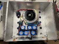
I got this Rawson built Aleph J mini last month for cheap. I put it in my 2 channel system and both channel had a loud hum and noise. Really Loud pop when I turned on and off. Took out of my system and had a look inside.


Took the transformer off it was a 500VA with 20 volt secondaries, then looked at the PS board,


Took the transformer off it was a 500VA with 20 volt secondaries, then looked at the PS board,
Attachments
Number one problem is a safety issue. The safety ground at the AC IEC socket does not appear to be connected to the chassis.
The power supply board has a "star ground". Star grounds are highly misunderstood. It should not be used in the power supply board. The "ground" from the bridge rectifiers should enter the PS board at the same capacitors as the V+ and V- from the bridge rectifiers. The ground conductor should then progressively travel from capacitor to capacitor on the way to the last capacitors. The PS ground connection to amplifier boards should connect to the last capacitors at the end of the PS board, at the PS V+ and V- outputs.
Wires should be twisted. V+ V- Gnd from PS board to each amplifier board should be twisted. V+ and V- from rectifiers to PS board should be twisted. Speaker + and - from amplifier board to speaker out connectors should be twisted. AC wires should be twisted. Input signal + and - should be twisted.
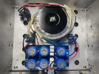
I reached out to Randy and got his PS board and swapped out the donut with a 200VA one with 15 volt secondaries. And replaced the PS. The amp was running really hot and could not leave my hand on it for few seconds. Already had most of the components for the power supply. Randy helped me find a couple of mistake I had in which I blew a couple of fuses and 2 rectifiers. Once I tested the power supply hooked up the amps and the right channel still was humming and had was making static pops sounds. Randy suggested it might be cold solder joint somewhere on the right board and suggest I use a nonconducting rod to push on the wires and components while pug in and using a crappy speaker to find the joint and he was right I found a capcitor that would make noise and pop when I gave it a little push. This is the little bugger on the board. Not a lot of solder on the top.

Also thought it strange that the capacitor is on a resister location. Once I resoldered it, the noise was gone and the amp was making music.

I still need to tidy up the wiring but it’s working fine now.
Also thought it strange that the capacitor is on a resister location. Once I resoldered it, the noise was gone and the amp was making music.
I still need to tidy up the wiring but it’s working fine now.
I agree, lots of work to sand off the board and then trying to hold wires in place for soldering the star ground.Seems like it would’ve taken him more work/time to do a crap job like that. Should be easy enough to sort out though.
It looks like the original PS board had traces for a "star ground" already. The wired version was electrically no different than the pcb trace version, and both would have hummed. The "dirty" ground from the rectifier outputs, ripple from the capacitor filtering, and "clean" ground from the "clean" PS output all connected together at one location is not a good thing.
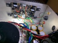
I am not too familiar with this board and it looks like C4 and R15 switch position on my amp board.

Here is a picture of another board with the R15 and C4

Here is a picture of another board with the R15 and C4
Randy.... Randy.. Let me come clean on that...
I ended up shipping my Rawson A5 monoblocks and F5 to Randy.
As I recall, per our converstations, the only parts he kept were the box and the transformers. He made a point of putting bright blue LEDs on the front panels.
Of course. ;-)
Lately that F5 has been powering the Metronomes... The A5s drove my Maggie 12s for quite a while, until I upgraded to the A2 and Maggie 1.7.
Yep, Randy built the A2s for me too. We went with the aluminum chassis for those. There is no way in he!! I could build an amp the way he can.
Nice jobs.
After the amount of badmouthing we have seen about Randy, it's very nice to hear some positive comments about his support.
😎
😎
- Home
- Amplifiers
- Pass Labs
- Rawson Repair Reflections