I'm just hoping there aren't more of these "resistor pack" builds out there.
This is truly scary. 🙁
This is truly scary. 🙁

I will be sending some PCBs to Will that should pair well with a new donut to make this one safe. The PCBs have a compact layout made to fit into these tight rawson cases. CCRC dual mono "V6" style should work on this one. If he can squeeze it in, he's also getting a spare CSample F1 board. Let's see what make it in the final build.
I hope so, too.I'm just hoping there aren't more of these "resistor pack" builds out there.
This is truly scary. 🙁
Randy was a bit surprised when I sent him the pic. It was the first time he'd seen that.
Hi all, I'm looking for some troubleshooting advice. I've got a Rawson build Mini Aleph. It's worked okay in the past, but I just pulled it out after maybe a year of storage and it has big 60 or 120 Hz hum. Where should I start to address this?
Thanks,
Pete
Thanks,
Pete
Hi all, I'm looking for some troubleshooting advice. I've got a Rawson build Mini Aleph. It's worked okay in the past, but I just pulled it out after maybe a year of storage and it has big 60 or 120 Hz hum. Where should I start to address this?
Thanks,
Pete
find address, then
I didn't want to presume, but thanks - I'm attaching some photos. And I bought it ignorant of the history of the builder. I set it aside when I got more info about the builds, and have been using my ACA Minis. I'd like to get some info so I can decide either to fix it or get rid of it.
Thanks in advance- for the help and for not burning me at the stake.
Pete
Thanks in advance- for the help and for not burning me at the stake.
Pete
Attachments
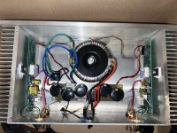
not sure about the hum but I would resolder all of those output mosfets and any other solder joint that looks like it may need it ..dB
Good question. I looked at hi fi shark for "Rawson" and see 74 old listings. I imagine that's only a portion of them. About a dozen have come across my bench over the past 2 years. I've seen: Aleph J, Mini J, F5, F2J, F3, Gainclone, and now Aleph 5. They all have the same grounding and PSU issues.
At some point I'm planning to put an ad up somewhere to fix these. Bare minimum is total power supply revamp. Even if the request is to fix something broken, the mains wiring, grounding, and PSU PCB will need to be upgraded if it's coming across my bench. Audio related upgrades optional (caps, etc.)
You know... I looked for years for a pair of Aleph 2s.... called the factory, looked everywhere... found a pair in Japan.
Sure, the A5s were floating, but I did unclip the thermistor thingies from the bundled cables and they actually sounded pretty good. Besides, mine are painted black... neat...
I did think of painting flames on them... but after You Know Who did a full rebuild, no need...
After years of running dual vacuum stereo tube amps in a vertical biamp configuration, the Rawsons did seem the pinnacle of reliability... well, after I fixed the right channel's UPS damage.
Last edited:
I have a pair of Aleph 5 mono clones on the bench now. They have the usual power supply & grounding issues. One mono had DC offset a bit high, so it’s getting new matched inputs.
I made some “6 pack” CRC power supply boards that are slightly bigger than the existing boards. There’s not much room to work with the big donuts, so why not make some boards. I like working with the 5w vertical resistors - so easy...
The dead bug mounted output MOSFETs are getting replaced with some daughter boards. That should make better use of the entire heat sink, and it will be a bit more tidy.
A broken F3 clone (just purchased) and another F3 (coming soon) are the next 2 in the queue.
Let me guess..... I seem to remember the asymmetric MOSFET mounting on the heatsinks. Designed to migrate heat to create a deeper soundstage! 😉
Pete,
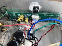
It appears you have no ground wire from IEC to chassis. That's one to fix up before going further.
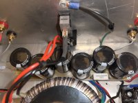
How do the power supply caps look? I can't tell in the pix if they're bulging or not.
This looks like one of the smaller enclosures. Do you think it's possible to mount the donut on an L bracket and still close the top? If so, you could fit a proper power supply board in with fresh caps. And 2 rectifiers.
If you're up for the fix, I'll mail you a power supply board. I have made a few smaller ones specifically to fit into these boxes. I may even have a pre-drilled L-Bracket I could send you.
When you get to it you have to post a picture of the bottom of that power supply board, I've never seen one like that.
It appears you have no ground wire from IEC to chassis. That's one to fix up before going further.
How do the power supply caps look? I can't tell in the pix if they're bulging or not.
This looks like one of the smaller enclosures. Do you think it's possible to mount the donut on an L bracket and still close the top? If so, you could fit a proper power supply board in with fresh caps. And 2 rectifiers.
If you're up for the fix, I'll mail you a power supply board. I have made a few smaller ones specifically to fit into these boxes. I may even have a pre-drilled L-Bracket I could send you.
When you get to it you have to post a picture of the bottom of that power supply board, I've never seen one like that.
I suppose that since I have little credibility to lose after meeting Nelson in person (*) I can own up that Randy rebuilt my mono A5s and a stereo F5 Rawson builds.
He did a great job and did not criticize me for my, ahem, making such an ungrounded decision...
As I recall, the only things he kept were the cases, the doughnuts and the connectors. Very good sounding with no hum and no noise. The quality of the work (design and manufacturing) is extremely good.
I should note that the Rawson builds did sound very good too, a measure of how good the original Pass design was (is). But, there's a certain amateurish build quality to Tim's work. Not to mention the ungrounded chassis.
(*) Likely he thinks I'm certifiable... many people would agree with him, I'm afraid. People say that "usually" there's method to a madness. I prove otherwise. LOL...
Last edited:
Pete,
At least your amp doesn't have the "resistors of terror" like the last one we saw.
Can you please confirm that the IEC AC socket has an integrated fuse holder? It looks big enough that it should and I'd just want to verify that.
If you are able to, I suggest you take up Randy's kind offer and rebuild the power supply completely. But whatever you do, you need to address the the lack of a connection between the chassis to the IEC socket's earth connection.
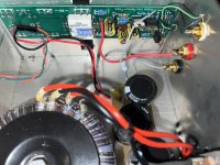
The transformer looks like an Antek which is fine. Can you see what are the secondary voltages and VA rating? There should be a model label on the transformer giving you this information.
Cheers,
Dennis
At least your amp doesn't have the "resistors of terror" like the last one we saw.
Can you please confirm that the IEC AC socket has an integrated fuse holder? It looks big enough that it should and I'd just want to verify that.
If you are able to, I suggest you take up Randy's kind offer and rebuild the power supply completely. But whatever you do, you need to address the the lack of a connection between the chassis to the IEC socket's earth connection.
The transformer looks like an Antek which is fine. Can you see what are the secondary voltages and VA rating? There should be a model label on the transformer giving you this information.
Cheers,
Dennis
Hi Randy,Pete,
It appears you have no ground wire from IEC to chassis. That's one to fix up before going further.
How do the power supply caps look? I can't tell in the pix if they're bulging or not.
This looks like one of the smaller enclosures. Do you think it's possible to mount the donut on an L bracket and still close the top? If so, you could fit a proper power supply board in with fresh caps. And 2 rectifiers.
If you're up for the fix, I'll mail you a power supply board. I have made a few smaller ones specifically to fit into these boxes. I may even have a pre-drilled L-Bracket I could send you.
When you get to it you have to post a picture of the bottom of that power supply board, I've never seen one like that.
Thanks for the help.
Yes, it's about 15 inches wide, 8 inches deep and 5 inches high, but it seems there's room to remount the donut vertically. The caps look okay to me, not bulged to my eye. If you're still willing, I'd like to take you up on the PS board - I'll be happy to reimburse cost and shipping. And it would be great if you have the L-bracket. It will keep me from having to invent something.
Other notes - yes, the IEC ground is not connected at all - should it just go to a chassis ground, like the one from the power transformer? (As you can see, I'm a kit builder, not a designer!)
dBel84 - yeah, there doesn't seem to be much solder visible on the outputs. I will add some - better safe than sorry.
Mikerodrig27 - adding standoffs to the ends of the boards - would that require drilling the heatsink? Or is there an easier way? It makes sense to address the fact that they're unsupported.
DennisHui - the IEC doesn't have an integrated fuseholder. In fact, there's no fuse at all. I know that needs attention.
The transformer is an Antek - it's hard to see the writing but I think it's 15-0-15v.
Thanks to all for the attention and expertise!
Pete
No fuse?!?!?!?!?! WOW. Post of picture of that IEC, please.
What transformer is that? I want to confirm the diameter plus VA rating. VA rating for fuse sizing.
If it's a 15+15V Antek I'd expect a part number like
AN-2215 (200VA 15+15)
AS-2215 (200VA 15+15 with Shield)
AN-3215 (300VA 15+15)
AS-3215 (300VA 15+15 with Shield)
I don't see a purple wire, so I doubt it's "AS" series.
I can throw a fuseholder and a couple fuses in, too.
Send me a PM with your address info.
I tried to squeeze the camera in there to get a photo of the IEC but no luck. But I can see that nothing is connected to the 3nd leg of the iec.
i was able to see that it's the AN-2215 transformer.
I will send a PM now. Thanks so much for the guidance and generosity.
i was able to see that it's the AN-2215 transformer.
I will send a PM now. Thanks so much for the guidance and generosity.
@pboser "yes, the IEC ground is not connected at all - should it just go to a chassis ground, "
As I recall... the neutral is used as the "ground" and the chassis is wired to it as well... at least my original Rawson A5s and F5 were wired that way. If you follow the neutral wire, you ought to see something like that... in my amps it went to a stud where the whole thing came together... hmm...
So, just running a wire from the real ground to the chassis is not a good idea as it will short both... I thought about "floating" the neutral and then grounding the chassis, but Randy's idea is correct, just rebuild it correctly. The issue is that you don't know where else in the circuit there is a short between the chassis and the circuit "ground". You'll be chasing your tail to fix it.
I'm actually surprised we don't hear ground loops all over the place.
Another "safety fix", which I considered, was to put the entire amp inside a larger Faraday Cage type case that itself was grounded... but, yeah, just rebuild the thing.
Last edited:
Mikerodrig27 - adding standoffs to the ends of the boards - would that require drilling the heatsink? Or is there an easier way? It makes sense to address the fact that they're unsupported.
If you didn't want to drill holes, there are adhesive standoffs. If the adhesive happened to fail (likely due to heat) the mosfet pins at least keep things indexed. The best solution would be to drill some holes for M3 standoffs.
I would check to make sure the mosfet screws are snug.
This may be a nice little upgrade as well
- Home
- Amplifiers
- Pass Labs
- Rawson Repair Reflections