Claas,
Thanks for running that test! The idea for that board came when I made F5 Turbo V3's for a friend and was wiring up that ground bridge/CL-60. I kept getting confused, and the wiring was a little tight. I wanted to make a simple and foolproof solution for that portion of the circuit.

Thanks for running that test! The idea for that board came when I made F5 Turbo V3's for a friend and was wiring up that ground bridge/CL-60. I kept getting confused, and the wiring was a little tight. I wanted to make a simple and foolproof solution for that portion of the circuit.
R***** Aleph J monos
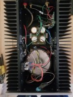
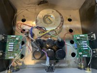
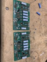
Hi Randy, I present to you another 'burn your house down' example. I used these for almost 10 years (bought them second hand), and never opened them up for a look during this time! Dumb, I know...
Once I did, I immediately quit using them. It's hard to tell from my pictures, but one of the wires coming off the pcb looks like the insulation has melted off it.
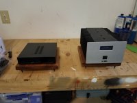
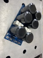
The cases are pretty small, so you may not want to undertake a rebuild on these. The mono bloc next to one of the two Aleph J amps in Nohr cases is Emotiva's class D amps PA-1 for scale. I have no plans to ever use them again, so they are available for rebuild but not for use unless rebuilt if interested.
Thanks,
limits
Hi Randy, I present to you another 'burn your house down' example. I used these for almost 10 years (bought them second hand), and never opened them up for a look during this time! Dumb, I know...
Once I did, I immediately quit using them. It's hard to tell from my pictures, but one of the wires coming off the pcb looks like the insulation has melted off it.
The cases are pretty small, so you may not want to undertake a rebuild on these. The mono bloc next to one of the two Aleph J amps in Nohr cases is Emotiva's class D amps PA-1 for scale. I have no plans to ever use them again, so they are available for rebuild but not for use unless rebuilt if interested.
Thanks,
limits
Attachments

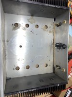
If the transformer could be mounted to the front face, it would open up some space for Randy's boards.
Limits - that is really tight!
Is the chassis tall enough to put the transformer on the front plate or on an L-bracket up-front? I made some "V6" power supply PCB's to squeeze into rawson amps, but they may not fit in this one even.
If the dimensions are right that could be a nice chassis for a monoblock using a Meanwell power supply. I'm specifically thinking of the upcoming SIT/VFET project is (Theseus?). Did you buy any TOKIN SITs?
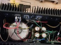
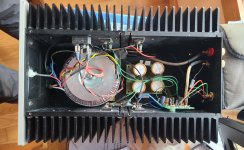
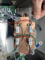
The internal chassis dims. are 4 1/2 inches wide x 11 3/8 in. deep x 4 7/8 in. high. The transformer is 4 inches wide. The heatsink fins are 5 x 1 5/8 inches. Here are some more pics. This one looks a little less rough, wiring-wise than the pics of the other one I sent earlier.
So, I guess in theory an L bracket might work, but I'm not going to mess with it 😉
limits
So, I guess in theory an L bracket might work, but I'm not going to mess with it 😉
limits
Attachments
Randy, you are brave to be taking on restorations that fix potentially dangerous aspects of work done by others. As a former lawyer, I must ask ... do you have liability insurance?
I received the new power supply board for the Rawson amplifier I recently bought. The amplifier was working fine, but I contacted Randy on what he suggested for improving the safety and reliability. He suggested leaving the amplifier section alone and upgrading the power supply board. Today I removed the old board and installed the new. No issues . Randy supplied great instruction. I'm a good kit builder/installer, but I'm no technician. Here is a picture of the old board's bottom and a video pof the amp with the new board on start-up....Thanks Randy!
Video: https://public.fotki.com/Rbertalotto/hifi-stereo-stuff/pass-labs-first-wat/p1040695.html
Video: https://public.fotki.com/Rbertalotto/hifi-stereo-stuff/pass-labs-first-wat/p1040695.html
Attachments

Last edited:

Another one fixed - super job! It was great to see you dive in and enthusiastically knock out this project. Congratulations Roy, and enjoy the music!
i talked to a guy the other day, and another F5 clone will likely be on my bench in January…. Stay tuned.
i talked to a guy the other day, and another F5 clone will likely be on my bench in January…. Stay tuned.
My Journey to a PASS designed amp:
http://rvbprecision.com/stereo/nelson-pass-first-watt-f5-turbo-v2.html
http://rvbprecision.com/stereo/nelson-pass-first-watt-f5-turbo-v2.html
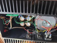
Next up. F5 clone. Normal grounding and power supply issues. It’s kinda dirty inside. One bridge only. Thermistors are not touching heatsink or mosfets.
Two firsts on this one. The PSU appears to be dual rail decoupled. And the top cover is diamond plate.
This one will get snubbers, dual bridges, a new PSU board, cleanup, and the amp boards mounted differently. I’m also going to swap those pots out for 25 turn Bournes pots.
Two firsts on this one. The PSU appears to be dual rail decoupled. And the top cover is diamond plate.
This one will get snubbers, dual bridges, a new PSU board, cleanup, and the amp boards mounted differently. I’m also going to swap those pots out for 25 turn Bournes pots.
Attachments

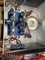
I decided to knock this one out quickly. After the kids were in bed I got to work deconstructing, cleaning, and rebuilding. It was a late night. Before bed I tested it at 75% bias and played a little music. This morning it's warming up at 90% bias, then I'll do final tuning in a few hours. I used my hum finding "stethoscope" and rotated the donut.
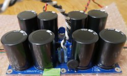
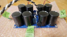
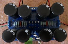
My original plan was to use a "6 Pack" CCRC power supply board due to the tight footprint of the chassis. I realized the 250VA Avel Lindberg left just enough room to use a "New Original" F5 dual-rail decoupled power supply. So that's what went in. The 6 pack will find a home elsewhere. Maybe in a bench power supply that is about 30 spots down the project queue...
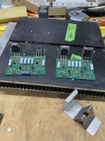
I didn't like the way the amp boards were mounted, so I opted to put them against the heatsink. Originally the PCBs could move, and the thermistors weren't touching the MOSFETs or heatsinks. The MOSFET legs were the only mounting points. There were 2 places that appeared semi-OK to drill the PCB's to make a mounting hole, so I picked one at the edge of the board furthest from the MOSFETs. This required moving the 3R 3W hum breaking resistor to hang off the board - not a big deal. I added a standoff to the heatsink and new holes for the MOSFETs.
Other mods: snubber boards on the bridges, a new switch, and a new IEC.
A few people recommended the Hakko de-soldering gun to me. HOLY SMOKES - why did I wait so long to get one? What a fantastic tool!! My broken 25-year-old Radio Shack "turkey baster" style desoldering iron will be thrown in the trash... I could try to get a new tip for it, but the difference between two is like a Porsche GT3 vs a Yugo. I'm getting rid of the Yugo!
My original plan was to use a "6 Pack" CCRC power supply board due to the tight footprint of the chassis. I realized the 250VA Avel Lindberg left just enough room to use a "New Original" F5 dual-rail decoupled power supply. So that's what went in. The 6 pack will find a home elsewhere. Maybe in a bench power supply that is about 30 spots down the project queue...
I didn't like the way the amp boards were mounted, so I opted to put them against the heatsink. Originally the PCBs could move, and the thermistors weren't touching the MOSFETs or heatsinks. The MOSFET legs were the only mounting points. There were 2 places that appeared semi-OK to drill the PCB's to make a mounting hole, so I picked one at the edge of the board furthest from the MOSFETs. This required moving the 3R 3W hum breaking resistor to hang off the board - not a big deal. I added a standoff to the heatsink and new holes for the MOSFETs.
Other mods: snubber boards on the bridges, a new switch, and a new IEC.
A few people recommended the Hakko de-soldering gun to me. HOLY SMOKES - why did I wait so long to get one? What a fantastic tool!! My broken 25-year-old Radio Shack "turkey baster" style desoldering iron will be thrown in the trash... I could try to get a new tip for it, but the difference between two is like a Porsche GT3 vs a Yugo. I'm getting rid of the Yugo!
Attachments
-
 BD1FCEE6-CD4B-4ED3-B03D-628647D95B44.jpeg446.8 KB · Views: 143
 -
 2E015B24-F369-4B30-AB97-9B651B9A9FC1.jpeg510.7 KB · Views: 136
 -
 F867B90A-D667-411B-B0A7-BAB0F71BEE67.jpeg700.8 KB · Views: 142
 -
 DF7CDC94-F900-4485-87A5-EB8FC4E77BAF.jpeg388.4 KB · Views: 139
 -
 0E5AB10A-6B8E-4BA2-BFA4-2FB52DE3AB20.jpeg625.8 KB · Views: 159
Last edited:

😀 😀 😀A few people recommended the Hakko de-soldering gun to me. HOLY SMOKES - why did I wait so long to get one? What a fantastic tool!!
For the amount of rework/repair you do, it's indispensable. I'll never get rid of mine even though it doesn't get all that much use.
Speedy work Randy, nice!
I just received the same Hakko de-solder gun under the Xmas tree. I can’t wait to try it, thinking about removing parts from old projects just for fun, LOL. Who knows, with this parts shortage I just might find hidden gems.
I just received the same Hakko de-solder gun under the Xmas tree. I can’t wait to try it, thinking about removing parts from old projects just for fun, LOL. Who knows, with this parts shortage I just might find hidden gems.
The Hakko is a life altering experience, especially if you experiment or rebuild or just for those times when your latest 10/20/30 hour assembly project doesn't fire up like it's supposed to and you're faced with the decision to start replacing parts. I've jammed up the barrel of mine a couple of times and was able to clear it out successfully with extremely fine PCB drill bits. Another tip - tip it 'skyward' from time to time while it's hot as I've also found that sometimes molten solder can collect in the barrel that will choose to drip out on your hand when you remove the canister to empty it out.
Great work on the latest rescue Randy!
Great work on the latest rescue Randy!
I like the way that F5 turned out. I have one too and I think I'll update it to an F5 Juma version using FQP3N30 and FQP3P20. I'd rather use 2SK2013/2SJ313 but those mosfets seem to have gone up in the magic smoke.
I have the older Hakko desoldering gun. Still going strong but the new one is looking nice and shiny.
I have the older Hakko desoldering gun. Still going strong but the new one is looking nice and shiny.
No, I think he stopped at least 10 years ago, somewhere in the F5 era. Randy might know more there.Is Rawson still selling amps? Are there a lot of these time bombs out there?
I'm not sure how many are out there. They do seem to pop up in bunches, usually not working.
- Home
- Amplifiers
- Pass Labs
- Rawson Repair Reflections