Angrypat. It has 2 bridges, more psu caps than normal, and looks like elna silmic 2’s on the amp boards. So perhaps he’s right. It’s a signature reference edition.
But... no ground wire... And I’m reasonably sure I know what the bottom of that PSU board looks like. It’s a candidate for a refresh.
But... no ground wire... And I’m reasonably sure I know what the bottom of that PSU board looks like. It’s a candidate for a refresh.
Here are pics of the next one. I don't have it yet. I'll get it after the AJ is done. Any idea what that circuit is?
Why don't you ping Tim? He's actually a friendly guy.
Why don't you ping Tim? He's actually a friendly guy.
I rebuilt that one. Customer is thrilled with it.
I think Tim used to live within 30 minutes from me. I understand he’s now in another state.
Tim seems to be a recurring story here. I've thought it has to do more with selling products not meant for sale but I remember some complaints about assembling when he was criticized long time ago.
They were strange to me since I owned his F3 for about 4 years, without a hiccup with avg 12-16 hours daily use. The guy who bought it from me still has it in his system as the main amp and as far as I know it has never been serviced. More than 10 yrs all in all.
No casualties, no fire so far.
The amp had a good price and was a worthy introduction to the First Watt sound, at least to me. Strangely, despite flawed DIY work it had sonically outperformed anything else I've heard from the DIY FW units. It could have been about my hi eff speakers that are fuzzy to match. Actually the biggest shock to me was that a stock SIT-3 I owned shortly wasn't nowhere near its sound in my room. Whatever is the reason... Maybe I'm deaf.
Last edited:
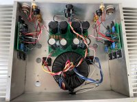
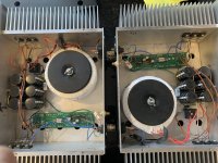
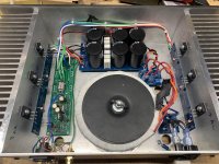
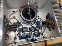
I joined the Rawson club last week with an F1J I bought from a member. I was guessing that it was a Rawson and Randy confirmed it this week. We're guessing it must be a late model, due to a fairly well done power supply, overall wiring and components. It plays well and has a slight issue with DC offset in one channel.
Overall, one of the nicer Rawson builds, I think.
I need to check the power supply and the grounding. I'll probably follow Randy's lead and update to a newer PCB. I'm not sure which way to take it. I've got boards for F1J, F2J, F3 and J2.
Maybe I'll just build them all and try them one at a time.
Overall, one of the nicer Rawson builds, I think.
I need to check the power supply and the grounding. I'll probably follow Randy's lead and update to a newer PCB. I'm not sure which way to take it. I've got boards for F1J, F2J, F3 and J2.
Maybe I'll just build them all and try them one at a time.
Attachments
Welcome to the club!
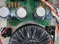
This is indeed the cleanest I've ever seen! PSU PCB's, looks like a safety ground might be in place (please double check those wires...), semisouths. Nice!
I've repurposed several of these cases from one thing to another. Chip amp to F5. Aleph Mini J to F2J. F2J to F1. ??? to F5. A couple bottom plates look like swiss cheese.
The inner chassis dimensions are always the challenge. The trick will be fitting the PSU and donut in there. Can the donut be mounted on an L bracket to open up space for a dual rail PSU for any dual rail designs you might be considering? I also had one where the "long skinny" boards were too long for heatsinks. My F1 boards barely fit, but i got them in. With a drill and tap, and some clever layout you should have fun playing around with that!
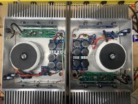
I have a pair of Aleph 5 mono clones on the bench now. They have the usual power supply & grounding issues. One mono had DC offset a bit high, so it’s getting new matched inputs.
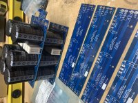
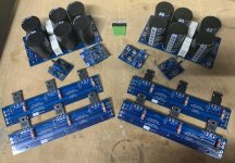
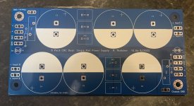
I made some “6 pack” CRC power supply boards that are slightly bigger than the existing boards. There’s not much room to work with the big donuts, so why not make some boards. I like working with the 5w vertical resistors - so easy...
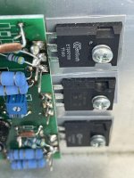
The dead bug mounted output MOSFETs are getting replaced with some daughter boards. That should make better use of the entire heat sink, and it will be a bit more tidy.
A broken F3 clone (just purchased) and another F3 (coming soon) are the next 2 in the queue.
I made some “6 pack” CRC power supply boards that are slightly bigger than the existing boards. There’s not much room to work with the big donuts, so why not make some boards. I like working with the 5w vertical resistors - so easy...
The dead bug mounted output MOSFETs are getting replaced with some daughter boards. That should make better use of the entire heat sink, and it will be a bit more tidy.
A broken F3 clone (just purchased) and another F3 (coming soon) are the next 2 in the queue.
Attachments

These rebuilds are so satisfying to watch. Great work on the boards Randall, they look very nice! Bespoke work is just that much more special. Tony is sure to be thrilled with these 🙂

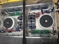
One of 2 Aleph 5 mono clones is 99.5% rebuilt. DC offset is tamed with new 9610’s. Apparently a red LED got mixed in with my blue ones, so I’m going to have to go back and swap that out. This amp really sings on the test speaker!
Attachments
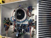
Aleph 5 monos are done. Gain and dc offset are as expected, and sound is great! These will go back to a happy owner shortly.
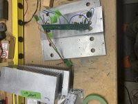
Next up is an F3 clone I recently bought. I’m debating power supply only rebuild or going all-in with the new boards from CSample’s group buy. Chassis dimensions may make the decision for me…
Next up is an F3 clone I recently bought. I’m debating power supply only rebuild or going all-in with the new boards from CSample’s group buy. Chassis dimensions may make the decision for me…
Attachments
I will be watching with interest on the F3 clone rebuild, as Randy bought this amp from me a few weeks ago. I found it to be an excellent sounding amp until it started making unfortunate noises in the left channel. I decided to part with it "as is" when Randy expressed interest.
Randy,
Nice rebuild pictures. I can't quite see it, but on the Aleph 5 mono rebuild did you mount the MOSFET output boards to the heatsinks as well or are they being held by the MOSFET leads alone?
Best,
Anand.
Nice rebuild pictures. I can't quite see it, but on the Aleph 5 mono rebuild did you mount the MOSFET output boards to the heatsinks as well or are they being held by the MOSFET leads alone?
Best,
Anand.
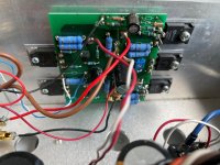
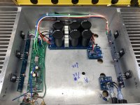
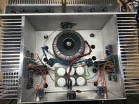
F3 is updated.
Grounding is fixed.
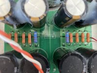
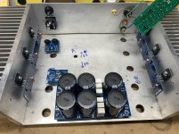
New power supply with upcycled caps. This is a single rail CRC per channel with thermistor to ground per channel.
I added snubbers to the bridges and added a CL60 & A/C cap pcb.
The left channel was scratchy intermittently. Turns out it was a bad solder joint at the input ground.
I may replace the input wiring with twisted pair. Other than that, this is about as far as I can go without putting in Chas’ new boards.
Grounding is fixed.
New power supply with upcycled caps. This is a single rail CRC per channel with thermistor to ground per channel.
I added snubbers to the bridges and added a CL60 & A/C cap pcb.
The left channel was scratchy intermittently. Turns out it was a bad solder joint at the input ground.
I may replace the input wiring with twisted pair. Other than that, this is about as far as I can go without putting in Chas’ new boards.
Attachments
- Home
- Amplifiers
- Pass Labs
- Rawson Repair Reflections