Thank you, Andy! Much appreciated. That's a great idea! There should be plenty of space, but ... a few cents in prevention. I likely even have something around that would fit the bill. I have definitely taken inspiration <stolen shamelessly> from your work, but I had not noticed that feature.Very nice, Patrick! Will be following this. No biggie but I would perhaps but a rubber knob on the nut facing the chassis front plate, just in case the trannies sway into a short. But maybe your room isn’t dancing as much as mine(I put some small rubber knobs on the bars for my vertically mounted trannies. See attached pics you have prolly seen before).
@von Ah - Thank you! It is going to give me a workout.
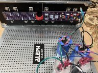
Is what you're describing that they'll radiate to each other? I hadn't even considered that since they were just filter chokes. I was trying to orient them in a way that I thought they'd pick up the least noise from other things... I didn't even consider that they'd pick up noise from each other.In your case, placing the choke pairs at right angles to each other would take up more space, but I would consider placing them in a "V" formation. Without measurements, I don't know what difference it would actually make, but it is something to consider.
 I suppose since there is still an AC component however small ... Learning... learning... (I think).
I have plenty of space... I'll have to ponder how to get them moved around some. It's only a few bolts. I lengthened the wiring a wee bit with some very flexible wire b/c my previous solution to mount them to the boards ... wasn't good. However, there is still not a ton of room to work in terms of connection length. However, I don't think it would take much extra length to try a 'V' or right angles even. I appreciate the thought. With that said... I was trying to keep them as far away from AC as possible/practical too.
Separate from the ripple ... how would one go about measuring that to know if I make it better? I truly haven't the foggiest. With a toroid, I can (depending on the amp) use the handy-dandy earbud method to rotate the toroid to where I hear the lowest noise... It is checking a scope on the outputs for noise the right way?
It's a rarity for me, but I'm actually taking my time to make reasonable attempts to do this 'right', and learn along the way.
 Normally, I just want MUSIC... NOW! Well, my Aleph 60 is begging for power... It's not me... it's the poor power-starved amplifier.
Thanks everyone!


you know pics of my builds with same arrangement of chokes
If you have a sound card and REW software, you can use the FFT function to see the noise frequency components. It's just a bit more sophisticated than your earbuds.
In big LuDef, I did not see how you arranged chokes under the filter boards. At 90 degree?you know pics of my builds with same arrangement of chokes
I missed other CLC builds... just went back through the blog... bad me...
OK... now I'm feeling foolish...If you have a sound card and REW software, you can use the FFT function to see the noise frequency components. It's just a bit more sophisticated than your earbuds.
Should I assume you mean to take a standard distortion measurement and look at the 60Hz multiples? One side (V+ or V-) at a time.
Edited to add - I'm still noodling though how I'd go about this. If there is a thread that shows it with a PSIU, or if you've got a brief destination... I'd be grateful. I know how to do a standard amplifier distortion measurement with REW ...
just went back through the blog
I believe there are pics in LuDEF thread, covering 2 builds - one dual mono and one monoblocks
same arrangement od PSU in both builds, dead as Dodo, black as Soul
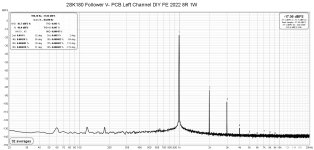
Just take a standard distortion measurement. I like to set the 1kHz output at 1W so that the noise can be referenced to a standard, in this case the noise would be measured relative to the 1W signal.
The FFT plot will show all noise and harmonics of the primary signal. For comparison, measure the amplifier, then change the configuration/placement of chokes/components and measure again, and compare the FFT plots.
Example of a quiet amp:
The FFT plot will show all noise and harmonics of the primary signal. For comparison, measure the amplifier, then change the configuration/placement of chokes/components and measure again, and compare the FFT plots.
Example of a quiet amp:
Attachments
^ Thanks, Ben! That, I can do.
I had it in my head that I needed to measure the PSU somehow by itself... I am still scratching my head around how one would do that. I'm sure it's possible, but I just don't have the brainpower to do it.
I would like to learn how to measure a PSU (I've learned a little bit with a scope) more properly by itself. The way you've described it above is wonderful for the 'entire picture', but since this is a separate PSU, it would be marvelous to know if I did this part of it properly ... either way, it's easy to make tweaks and measure an amplifier.
I have an idea or two.

Edited to add - When I say 'easy'... that's after I spent days and days trying to figure it out...
I had it in my head that I needed to measure the PSU somehow by itself... I am still scratching my head around how one would do that. I'm sure it's possible, but I just don't have the brainpower to do it.
I would like to learn how to measure a PSU (I've learned a little bit with a scope) more properly by itself. The way you've described it above is wonderful for the 'entire picture', but since this is a separate PSU, it would be marvelous to know if I did this part of it properly ... either way, it's easy to make tweaks and measure an amplifier.
I have an idea or two.
Edited to add - When I say 'easy'... that's after I spent days and days trying to figure it out...
My doc wife sez there is plenty of life in a dodo. Should we rather say black as dodo, dead as soul?I believe there are pics in LuDEF thread, covering 2 builds - one dual mono and one monoblocks
same arrangement od PSU in both builds, dead as Dodo, black as Soul
In my depicted build, I tried putting the chokes in a V. But space issues forced me to orientate them the same way as Patrick. Haven’t measured the PSU yet using FFT. But there is no measurable ripple with a Fluke. Not to say there isn’t any 🙂
It's good to be aware of theory when designing the physical layout of an amplifier. In real life, it's always a compromise, but at least you can choose what to give up. As with everything in life, it's the attention to details that makes something stand out.
@ItsAllInMyHead great looking build. Can you please link me to those threaded rods that you are using, I need them for one of my builds to mount the amp pcbs on top of the psu board. Did you cut those rods to the size and usually PCB mounting holes are M3 and your rods seems to be M4 so how did you insert?
thanks
thanks
^ Sure - They're wonderful!
I used nylon lock nuts, washers, split washers, and regular nuts (or will when it's all buttoned up). It makes for a nice stable platform.
This company has various sizes. Longer than standard delivery, but I wasn't in a huge hurry.
https://www.amazon.com/dp/B096KYJZTZ?ref=ppx_yo2ov_dt_b_product_details&th=1
Edited to add - I didn't answer a few of your questions. Sorry.
I bought them at 110 mm. I had the room. No cutting.
They are M4. The holes in the chassis plate fit M4 nicely, as did the holes in the boards.
Let's take this learning occasion too, shall I? The danger here is that in case of a short in the toroid, the front panel (and chassis) will be energised, right?... in case the trannies sway into a short.
But is it the transformer bolt attached to the epoxy resin (and not on the typical metal plate) as for all Toroidy transformers like yours? Assuming the bottom of the transformer is insulated by the rubber disk it comes with, and it does not touch the bottom of the chassis, should that be insulated/safe enough?
EDIT: Just noticed you used metal plates on top. So, the question still applies to my build (glad I have not finished it yet).
I think the danger is a shorted (secondary) turn created by the mounting hardware rather than a short of an actual winding to ground.
All right then. I guess keeping the toroid insulated from ground is not bad anyway. I try to do it with some rubber material mainly for attenuating mechanical hum.
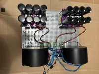
The PSU is mostly complete... for now... I will likely add some sort of relay-bypassed soft-start and/or a front panel switch, but I wanted to keep it simple to get things started. I'll also likely ask Prasi very nicely if he'd allow me to adapt his LT4320 boards just a tiny bit, or if he would kindly do it for me. I'd like them in purple <gasp>, the mounting holes to match the grid of the base plate, and for the snubber components to be through-hole. I'll be changing transformers at some regular intervals, and it would be wonderful to socket the snubber resistor.
Both PSUs are tested and known-working-good. I have not done any measurements other than voltage both loaded and unloaded.
Unloaded, I recall about 37V. Loaded with an Aleph 60 set to an initial Iq of around 2A, it was about 32V. I didn't look at the regulation numbers in the specs for the transformers (AS-4225), but it was a bit more sag than I anticipated. Either way, no big deal. I was shooting for ~32V rails. I'll take more precise / accurate measurements later and record them.
I still... haven't chosen connectors for the umbilical... I have no idea why I'm likely unnecessarily agonizing over a seemingly simple decision, but ... C'est la vie.
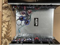
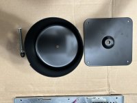
As a side note... I wanted to try Antek's new steel covers for another project. They're cheaper and lighter.
I am impressed. I have no idea how they differ in performance from an 'EMI shielding' standpoint in comparison to their chonky brethren, but I'd imagine they'll perform well for my uses. You can check the specs / weight etc, but IMO, for the cost they're a really nice alternative. One advertised aspect of the model I'm using in this PSU is, "It allows the user to change the transformer easily in the future." That's true, but for the weight savings, likely no meaningful difference in performance in my situations, and lower cost... I'll be using the newer style moving forward.
Some pics. Note - the cap banks in the amp chassis are wired temporarily for testing. Transformer shields are not connected, and there is no permanent mains earth / chassis ground wire yet. As always, thoughts are appreciated.
Both PSUs are tested and known-working-good. I have not done any measurements other than voltage both loaded and unloaded.
Unloaded, I recall about 37V. Loaded with an Aleph 60 set to an initial Iq of around 2A, it was about 32V. I didn't look at the regulation numbers in the specs for the transformers (AS-4225), but it was a bit more sag than I anticipated. Either way, no big deal. I was shooting for ~32V rails. I'll take more precise / accurate measurements later and record them.
I still... haven't chosen connectors for the umbilical... I have no idea why I'm likely unnecessarily agonizing over a seemingly simple decision, but ... C'est la vie.
As a side note... I wanted to try Antek's new steel covers for another project. They're cheaper and lighter.
I am impressed. I have no idea how they differ in performance from an 'EMI shielding' standpoint in comparison to their chonky brethren, but I'd imagine they'll perform well for my uses. You can check the specs / weight etc, but IMO, for the cost they're a really nice alternative. One advertised aspect of the model I'm using in this PSU is, "It allows the user to change the transformer easily in the future." That's true, but for the weight savings, likely no meaningful difference in performance in my situations, and lower cost... I'll be using the newer style moving forward.
Some pics. Note - the cap banks in the amp chassis are wired temporarily for testing. Transformer shields are not connected, and there is no permanent mains earth / chassis ground wire yet. As always, thoughts are appreciated.
Attachments
Another idea on the umbilical thing... if you didn't mind a short pigtail you could do these Anderson Powerpole connectors. (Watch out for low quality fakes) You see these used in HAM radio, solar power, radio control hobbies, etc. I used them to build +74VDC power distribution blocks at work (railroad electronics, mostly locomotive stuff). We have a pair of big power supplies on each side of our tech bay. Each of these supplies feeds 4 or 5 work benches, with Pomona banana jacks mounted up on the risers that we connect to.
^ Thank you. That's a very interesting idea. I lean toward a chassis-mount connection / jack, but I am warming to the idea. No one but me will ever see these...
Top of the pile for the moment are the Amphenol products you suggested. I will be incorporating the mains earth connection between chassis based on suggestions provided and a bit of reading. Once I figure out how that will run over, I can choose. The power pole connectors open up a practical possibility.
Questions for the collective wisdom of the group...
Is it wise to run two mains earth connections; one for each supply? I still have a hard time wrapping my head around where / how loops are formed, so I am not sure if that's a good idea. I know that there should be no current except in the event of a fault, so... I think ... maybe that it doesn't matter. Why? I'd like to run each set of supply wiring identically, so I never need to remember. Also, if at some point, I want to run the supplies independently, or just use one at a time, both will have the mains earth connected. The goal is to do it properly, safely, and make it, dare I say, more idiot (me) proof.
Yes, one mains earth per supply through NTC. So that the two supplies’ gnds meet only at star gnd, and loop protections from star to audio gnd through NTC or GLB. That is how I did it, ordered by MZM ❤️
- Home
- Amplifiers
- Pass Labs
- Universal Outboard Power Chassis for Pass