I believe that cap is considered a decoupling cap. It stores energy so that any voltage variation caused by the output stage does not affect the DC power to the input stage.
I like to put a cap at the power input location of the amp board. That is used to filter or bypass to ground any noise that the power supply wires may pick up between the PS board and the amp board. I believe that cap is considered a bypass cap.
I like to put a cap at the power input location of the amp board. That is used to filter or bypass to ground any noise that the power supply wires may pick up between the PS board and the amp board. I believe that cap is considered a bypass cap.

Beautiful! So, I think I've got that concept correct.
All of you... truly appreciated. I have to pause the brain and feed the body.
Until tomorrow!

All of you... truly appreciated. I have to pause the brain and feed the body.
Until tomorrow!
I got similar Rs values of 10-12 ohms for the Antek AS-3218 and AN-3236. Your AS-4222 and 4225 might give similar values to each other, with the 4225 being around 15R so it might work to settle on a single general value if you know in advance what range of secondaries and VAC ratings you'll want to use.Unregulated PSU. Regulated has its supporters, and I'm not done thinking about it... but for now... unregulated.
- LT4320 'ideal' rectification with Prasi's boards. They have placement for snubbers, but I am not sure how to best implement snubbers b/c I will be swapping transformers as needed. Thanks to the most recent advice, I'm heading this way.
- CCLCRC filtering with the V8 boards and chokes.
- 66kuF (2x33kuF) 50V
- Hammond 159ZJ 10mH @ 5A - 0R160 series resistance
- 33kuF
- 0R165
- 33kuF
There is AC noise everywhere. Wires, especially loops, act as antennae which pick up the noise. If the wires are a twisted pair, then there is common-mode rejection as the noise cancels. And as I mentioned before, a circuit that shares the same power rail can inject noise into the rail.
Capacitors have inductance and this raises its impedance to certain AC frequencies. This reduces its effectiveness at shunting the noise to ground. Using paralleled capacitors of varying sizes (with different inductances) reduces the ranges of frequencies affected.
Capacitors have inductance and this raises its impedance to certain AC frequencies. This reduces its effectiveness at shunting the noise to ground. Using paralleled capacitors of varying sizes (with different inductances) reduces the ranges of frequencies affected.
^ Once again, thank you for taking the time to explain. It's starting to sink in...
The eagle-eyed may have seen AS-4222 and AS-4225 sitting on the platform together in the pics. The AS-4218 are all otherwise occupied. Those are the three that I use most often. Depending on how resulting voltages from this wind up... some AS-4220s may join the fray. I love that idea. I was wary of over or under damping... but I suppose even being slightly off is better than nothing...
I also considered having a tiny PCB with the two caps and an 'insert' for the resistor. However, I observed that every implementation that I've seen for the snubber for transformer ringing, it is physically very close to the rectifiers. I am not so sure if that's a good idea having physical wiring between them vs. proper short traces. Thoughts from everyone are appreciated. I'd be willing to do this. It should be quite easy to do on either a PCB that I may be able to design myself and/or just a piece of perf board.
Note... unless I decide to add another IEC inlet and truly make the supplies completely separate, but housed in the same chassis, both supplies will always be identical for all intents and purposes. I just grabbed two to play with layout. The PSU will start off with 4225s.
-----
I didn't see any danger warnings re: testing the 4320s, so I'll get that going with a little transformer ... no need for a soft start with a wee transformer, no filter caps, and ramping up the voltage.
Extremely helpful, thank you!I got similar Rs values of 10-12 ohms for the Antek AS-3218 and AN-3236. Your AS-4222 and 4225 might give similar values to each other, with the 4225 being around 15R so it might work to settle on a single general value if you know in advance what range of secondaries and VAC ratings you'll want to use.
The eagle-eyed may have seen AS-4222 and AS-4225 sitting on the platform together in the pics. The AS-4218 are all otherwise occupied. Those are the three that I use most often. Depending on how resulting voltages from this wind up... some AS-4220s may join the fray. I love that idea. I was wary of over or under damping... but I suppose even being slightly off is better than nothing...
I also considered having a tiny PCB with the two caps and an 'insert' for the resistor. However, I observed that every implementation that I've seen for the snubber for transformer ringing, it is physically very close to the rectifiers. I am not so sure if that's a good idea having physical wiring between them vs. proper short traces. Thoughts from everyone are appreciated. I'd be willing to do this. It should be quite easy to do on either a PCB that I may be able to design myself and/or just a piece of perf board.
Note... unless I decide to add another IEC inlet and truly make the supplies completely separate, but housed in the same chassis, both supplies will always be identical for all intents and purposes. I just grabbed two to play with layout. The PSU will start off with 4225s.
-----
I didn't see any danger warnings re: testing the 4320s, so I'll get that going with a little transformer ... no need for a soft start with a wee transformer, no filter caps, and ramping up the voltage.
When testing your active rectifiers, they need to have a small load. They measure wonky if left unloaded.
Don’t sweat about snubbers if you’re going to use active rectification.
Don’t sweat about snubbers if you’re going to use active rectification.
^ Saved by the bell! I never considered that, thank you.
Rather than try to think this one through thoroughly and read more this early ... I'm willing to phone a friend. I am not trying to test it out at full capability / full expected current. I just want to make sure it functions properly before wiring it all up.
Would starting off with a 10k ish (3W) resistor work well enough? I have some around. With that load, the current at max 24VDC (little 18VAC transformer) should be ok. I'd assume running a higher load (lower resistance) would be more 'realistic', but unless I use a load resistor like I use for amplifier testing, I don't have anything laying around.
I'm assuming something between the Mohms of resistance in the DMM ... down to very low resistance like in a real application... but that leaves a lot of room.
🙂
Edited to show clarity - I use the load resistors for simulating speakers in amplifier testing... See... too early. 😉
Last edited:
Go smaller, 1K’ish. With 24vdc thats a tick above 1/2W, 3W resistor is plenty for short term testing.
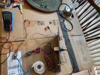
Alrighty - Everyone's fed, I'm re-caffeinated ... and the rectifiers are re-tested / re-verified.
It surprised me that with a 1k load and with no dim bulb limiting current... I set the variac to get almost exactly 18VAC across each secondary, and I was only getting a bit over 22VDC...
I didn't scope it or anything, and I don't think I should have a concern, or should I? I think maybe because it's not smooth DC perhaps... the DMM doesn't show the full amount... I expected to see >25 ... I didn't take notes when I tested them before with all the filtering etc.
Pics or it didn't happen... not pretty, but effective...
Edited to add - Shoot! I should have just hooked up a filter board to test my theory. Oh well, I already gave the table back.
Attachments
Last edited:
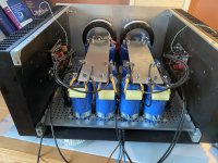
Didn't have too much time to work further on the PSU. I got the major chunks of the filter boards stuffed and made the (HUGE) mistake of connecting the chokes. The only reason I'm posting about it is to share a cautionary tale in case in case some other person has the same (not so) bright idea...
I listened to the advice re: putting the chokes under the filter boards. The filter boards aren't necessarily intended to pair with ~14AWG choke wires. I was too much of a fraidy cat to drill out the resistor holes. Since the boards have resistors in parallel for each spot. I thought, why not do it 'properly' and divide the choke wiring into two segments and solder each segment properly to some 18AWG solid core wire. 18AWG solid core happens to fit absolutely perfectly into the PCB resistor spots... so that must be the best way to do it... right?
Many of you are probably sighing to yourselves...
Solid core wire (and/or my technique) is absolutely horrible for this type of connection to the PCB. Any right angle stress on the wire... snap... grrrr....

So, I've stress-relieved it to the best of my ability ... and I have them sitting patiently still until they are ready for final installation. I doubt I'll be able to get much twist in the choke wires w/o putting too much stress on the connection, but I'll do what I can.
A pic to show what not to do... It may have worked much better with multi-strand. If I had to do it over again, I'd have made a small wire loop from the board and soldered the choke wire directly to the loop. Sometimes KISS isn't lazy... it's better too. 🙂
Live and learn...
I listened to the advice re: putting the chokes under the filter boards. The filter boards aren't necessarily intended to pair with ~14AWG choke wires. I was too much of a fraidy cat to drill out the resistor holes. Since the boards have resistors in parallel for each spot. I thought, why not do it 'properly' and divide the choke wiring into two segments and solder each segment properly to some 18AWG solid core wire. 18AWG solid core happens to fit absolutely perfectly into the PCB resistor spots... so that must be the best way to do it... right?
Many of you are probably sighing to yourselves...
Solid core wire (and/or my technique) is absolutely horrible for this type of connection to the PCB. Any right angle stress on the wire... snap... grrrr....
So, I've stress-relieved it to the best of my ability ... and I have them sitting patiently still until they are ready for final installation. I doubt I'll be able to get much twist in the choke wires w/o putting too much stress on the connection, but I'll do what I can.
A pic to show what not to do... It may have worked much better with multi-strand. If I had to do it over again, I'd have made a small wire loop from the board and soldered the choke wire directly to the loop. Sometimes KISS isn't lazy... it's better too. 🙂
Live and learn...
Attachments
You can extend that idea to the power input/output wiring. I solder pieces of 18 gauge solid copper wire "pins" to the power input and output pads of my power supply PCBs and use them for connection points. This way, I can mount the PCBs to the chassis without the input/output wires connected. Then, it's easy to wrap the wires around the "pins" and solder. Also, easy to unsolder if necessary.
I did a bit more digging around on connectors and umbilical options.
Bulgin seems very nice, but a bit pricey. Also, while I may have overlooked quite a bit of their product line, almost everything seems to be designed for environmental / weather protection.
Souriau-Sunbank seems to be an option, but I haven't dug into depth into their options.
Neutrik XLR are still an option
And a wonderful idea it is... I haven't gotten too deep into their tech specs, but they have a wonderful section in the catalog re: how to choose a product, and they clearly list the DC ratings. I haven't gotten into pricing yet.

Done for the day...
Once again... thanks to all! I hope anyone that reads these walls of text a while from now finds some useful nuggets.
Bulgin seems very nice, but a bit pricey. Also, while I may have overlooked quite a bit of their product line, almost everything seems to be designed for environmental / weather protection.
Souriau-Sunbank seems to be an option, but I haven't dug into depth into their options.
Neutrik XLR are still an option
I would think the Amphenol Industrial connectors (maybe 97 series?) would be great for high current DC connections with umbilicals. We use them all the time in our railway electronics that I service. With our heavily used in-house test boxes, we normally build them without the locking collar on the cable end. They fit plenty snug without it... the locking collar is just a hassle for constant use. Just an idea..
And a wonderful idea it is... I haven't gotten too deep into their tech specs, but they have a wonderful section in the catalog re: how to choose a product, and they clearly list the DC ratings. I haven't gotten into pricing yet.
Done for the day...
Once again... thanks to all! I hope anyone that reads these walls of text a while from now finds some useful nuggets.
When I was building my transformer coupled 2SK182ES amps, I was also looking for power connectors as I had the power supplies in a separate case. I needed high voltage (200V) at low current and low voltage at high current capabilities.
I found connectors that were suitable, but in practice, they were not easily available in complete sets. I would find chassis parts or cable parts, but not both together. At least, that was the case at Mouser and Digikey.
In the end, I purchased some aircraft connectors because they were available.
I found connectors that were suitable, but in practice, they were not easily available in complete sets. I would find chassis parts or cable parts, but not both together. At least, that was the case at Mouser and Digikey.
In the end, I purchased some aircraft connectors because they were available.
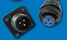
disclaimer "trust but verify".. always wise advise in life.. but here are a couple of Amphenol #'s as a possibility
Amplifier chassis receptacle: 97-3102A-16-10P
Cable mount plug: 97-3106A-16-10S
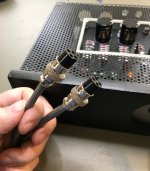
These aerospace style connectors are not cheap but I personally would not cheap out on an application like this. It's DIY, people can and will do as they wish of course. For a cheap option for low current stuff like the power supply I just finished, I'm trying out these "GX16-4 Aviation Plugs" from the big auction site. They were like $8 for 5 pairs. My plan is to power the front end (not built yet) living inside my amp from an outboard ±45Vdc supply. Current draw will be about 30mA.
Amplifier chassis receptacle: 97-3102A-16-10P
Cable mount plug: 97-3106A-16-10S
These aerospace style connectors are not cheap but I personally would not cheap out on an application like this. It's DIY, people can and will do as they wish of course. For a cheap option for low current stuff like the power supply I just finished, I'm trying out these "GX16-4 Aviation Plugs" from the big auction site. They were like $8 for 5 pairs. My plan is to power the front end (not built yet) living inside my amp from an outboard ±45Vdc supply. Current draw will be about 30mA.
Attachments
Once again, thank you!
This is a learning experience for me also. When my brain doesn't completely melt to nothing, I like to dig in a bit and understand how choices are made by people that really 'know their stuff'. Clear evidence supports that I will copy shamelessly (with permission) from those I know and trust, but at some point... I'd like to do something kind of 'new' (ish).
I was in 'purchaser'-side quality assurance for a chunk of my career. This was our motto. As a fun FYI -Ronald Reagan and I share a birthday.disclaimer "trust but verify".. always wise advise in life..
This is a learning experience for me also. When my brain doesn't completely melt to nothing, I like to dig in a bit and understand how choices are made by people that really 'know their stuff'. Clear evidence supports that I will copy shamelessly (with permission) from those I know and trust, but at some point... I'd like to do something kind of 'new' (ish).
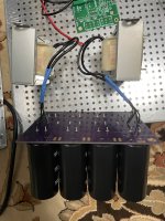
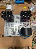
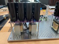
It's coming along slowly. Got a few parts for mechanical mounting. It's starting it to look more like a proper PSU.
Of note ... and trying to listen and implement suggestions.
AC will enter from the back in the middle of the filter boards. It will immediately go under the baseplate. I'm trying to keep AC short (with the exception of the run of the mains from back to front) twisted and away from DC. I'm one of those people that can't bear to cut the primary or secondary wiring for transformers b/c they move between projects so often. However, they're twisted and out of the way.
The DC lines from the rectifiers to the filter boards are twisted to shorten them up a bit. I have them a bit long in case I change the layout. I also twisted the lines for the chokes and mounted them under the filter boards to keep the leads short. The DC output will be an extremely short run to the back plate from the filter boards.
Still working on a decision for connectors... jacks... etc...
Again, thanks to all for the help and suggestions. If anyone sees anything to call out that I should change, please let me know. I've tried to implement all the suggestions and read up on their impact / importance.
Cheers!
Edited to add - I've got some new covered fuse holders on order... even though finger pokin' is verboten... it's better to be safe.
Attachments
Last edited:
Very nice, Patrick! Will be following this. No biggie but I would perhaps but a rubber knob on the nut facing the chassis front plate, just in case the trannies sway into a short. But maybe your room isn’t dancing as much as mine (I put some small rubber knobs on the bars for my vertically mounted trannies. See attached pics you have prolly seen before).
(I put some small rubber knobs on the bars for my vertically mounted trannies. See attached pics you have prolly seen before).Attachments

Wow. Sturdy builds.
@ItsAllInMyHead, that is going to be quite a chunk of metal. Do you think 23U will be tall enough?
Joking aside, there will be naught for which to want in that power supply. 😎
@ItsAllInMyHead, that is going to be quite a chunk of metal. Do you think 23U will be tall enough?
Joking aside, there will be naught for which to want in that power supply. 😎
One thing to be aware of is the magnetic field from a conductor radiates concentrically from it, so in the case of your chokes, they project out from each side of the exposed coils. Generally, I orient my chokes so as to minimize the influence of the magnetic fields on other components.
In your case, placing the choke pairs at right angles to each other would take up more space, but I would consider placing them in a "V" formation. Without measurements, I don't know what difference it would actually make, but it is something to consider.
In your case, placing the choke pairs at right angles to each other would take up more space, but I would consider placing them in a "V" formation. Without measurements, I don't know what difference it would actually make, but it is something to consider.
- Home
- Amplifiers
- Pass Labs
- Universal Outboard Power Chassis for Pass