It is 23 gauge per wire with 8 wires altogether. Although it isn't really practical, the 8 wires have a cumulative area of around 13 gauge wire. you would have to solder them all together at either end though.CAT6 is great for input wiring.
Not recommended for speaker connections, way too thin.
I use this stuff. Lots of colors which is really handy:
silicone wire
to much parasitic capacitance ,good for short piecesIt is 23 gauge per wire with 8 wires altogether. Although it isn't really practical, the 8 wires have a cumulative area of around 13 gauge wire. you would have to solder them all together at either end though.
I use this stuff. Lots of colors which is really handy:
silicone wire

The hum is still there but it is so low I’m going to leave it now while I let it run for the day. I’ll clean up the wiring, tighten up the case and see how it sounds tomorrow.
The hardest part of this project for me was putting the case together. That was a challenge.
The hardest part of this project for me was putting the case together. That was a challenge.
Attachments
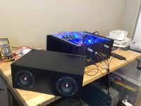
I’ll give that a try, thank you. By the way, the hum, more of a buzz, is so faint at the speaker that I have to have my ear on the speaker grill to hear it. No way to hear it at all with music, or between songs. I might try to track it down at some point. I would swear I only noticed it when I stood up the front panel which put the power supply closer to the transformer.Yeah, beautiful sound.
If using RCA's, check the ground lift mod.
Adjusting the bias between 470mV and 400mV changes the sound as well... quite a lot. You can definitely find the sweet spot that suits your taste, the rest of the system, and the speakers.
It doesn’t bother me but I am curious about it. I read through a couple threads referencing specific frequencies, 120hz and 60hz, ground loops and power supply, mine right above the transformer is around 366hz (using a couple free aps on my iPhone).
I‘m not ready to dive into it since I can barely hear it, I’m just curious if this frequency may point to something specific. I’m still loving the sound and appreciate all the help this site has provide.
I‘m not ready to dive into it since I can barely hear it, I’m just curious if this frequency may point to something specific. I’m still loving the sound and appreciate all the help this site has provide.
This may help:
https://www.diyaudio.com/community/threads/aleph1-2-irf240-vs-irfp250.99132/
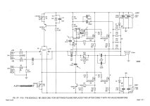
Also, see the attached pdf
NOTE: the deciding factor is how big the amplifier heatsinks are... how good the ventilation/air circulation will be, and how much power are you ready to tolerate as being safe, for each MOSFET, to dissipate. Nelson has posted somewhere.... what he accepted as a safe dissipation, to ensure good reliability... I think it was 25W per IRFP240.... but they can be pushed much harder... and IRFP250 even harder than 240... but, that is a device dissipation, so you need to ensure good heat transfer between IRFP250 and the heatsink.
https://www.diyaudio.com/community/threads/aleph1-2-irf240-vs-irfp250.99132/
Also, see the attached pdf
NOTE: the deciding factor is how big the amplifier heatsinks are... how good the ventilation/air circulation will be, and how much power are you ready to tolerate as being safe, for each MOSFET, to dissipate. Nelson has posted somewhere.... what he accepted as a safe dissipation, to ensure good reliability... I think it was 25W per IRFP240.... but they can be pushed much harder... and IRFP250 even harder than 240... but, that is a device dissipation, so you need to ensure good heat transfer between IRFP250 and the heatsink.
Attachments
Last edited:
Hello Guys!
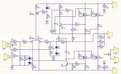
I have just drawn the wiring diagram of the Aleph j collecting some informations that I hope will be useful to everyone.
I would like to know your opinions on whether or not to adopt the following components:
R3 (for RCA input option)
C5
C8
furthermore there are all the calibration trimmers for:
1) LTP bias
2) Bias
3)Offsets
4) AC gain
which are set up on the pcb and which will subsequently be replaced with fixed value resistors.
Every advise are welcome.
Thank you.
Attachments
Hello all. I have started down the path of building the Aleph J thanks to this awesome guide. I have built the universal PSU as specified in the build guide. I made one substitution for the 8x Panasonic .47 ohm 3 watt resistors. The Panasonic resistors from the saved Mouser cart were out of stock so I decided to substitute what I believe is a suitable replacement from Vishay/Dale. Would any of the experts here confirm whether this will work as a substitute for this use case? I plan to use these on the amp board as well.
https://www.mouser.com/ProductDetail/Vishay-Dale/CPF3R47000JNB14?qs=MJw/449BOx/BmHgUJauRtw==
Thanks for your help!
https://www.mouser.com/ProductDetail/Vishay-Dale/CPF3R47000JNB14?qs=MJw/449BOx/BmHgUJauRtw==
Thanks for your help!
They are very good. Very expensive as well... they'll sit a bit awkwardly on the PCB. Check the dimensions vs. the PCB hole spacing. You may have to bend the legs at a sharp 90 deg angle. Would this cause any strain..? Difficult to say...

Check here... seems like they are in a runout sale... very cheap!
https://www.newark.com/panasonic/erx-3sjr47/resistor-0-47ohm-3w-5-axial/dp/52W8322?CMP=AFC-OP
Check here... seems like they are in a runout sale... very cheap!
https://www.newark.com/panasonic/erx-3sjr47/resistor-0-47ohm-3w-5-axial/dp/52W8322?CMP=AFC-OP
Last edited:
- Home
- Amplifiers
- Pass Labs
- Aleph J build guide for noobs