besides numerous articles on FW site, you can also take a look at this (zip file for down.) : https://www.zenmod.in.rs/erno-borbely-site-zip-file-for-benefit-of-diy-community/Understood. I've got some Ideas. I'll report back. Peace and as always my deepest respect and appreciation. PS this circuit wired to the X150.5 is well just wonderful...
nice to learn why you can't remove R27/28, in this and majority of cases
in some cases you must remove it ...... when JFet gate is getting exact ref. voltage potential from preceding stage
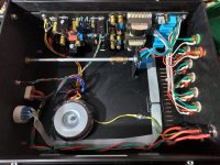
Yes Ben.I appreciate your observations. I am totally cognizant of the AC B fields.I studied physics as part of my science and engineering degrees..Maybe you noticed the welded square tube ac mains channel. Early days on this iteration.. I may attenuate volume from my DAC and do away with those long wires to front.
Yes, I did see the shielded AC wires in the centre of the chassis. What caught my attention were the signal wires adjacent to and crossing the AC wires at the volume pots. That probably caused audible hum unless your speakers are not very sensitive.
Of course if you delete the volume pots, that would make the issue go away.
Gain? Not sure what you mean here. DACs don't generally have voltage gain. Digital in / Analog out. I might be missing something in your interpretation. If so, apologies. Are you talking about any voltage gain internally after conversion and filtering / prior to analog output? If so, not sure that's relevant, and I can't be sure that occurs. All the 'volume control' is in the digital domain, I believe, and I don't think there is any 'real' gain.I can't find the spec, but I suspect 12+db gain.
? That holds true for some digital attenuation / volume control. Considering the conversions taking place within this product... I'd say not to worry about it, but that's just me. I'd run it at it's lowest volume w/o worrying one bit 😉 about loss in audio fidelity. If you're concerned though, simply press a button, lower the output voltage, and crank the volume. I think you have 4 (maybe 6) settings.I seem to have read that chip works best at greater than half volume.
See ZM's posts.I'm thinking I could delete the pots on iron pre and increase R28, R30 by 5k or more
Yes.so that I can control volume from the DAC (with a remote!). No?
Per the specs, the DAC (at it's highest setting) can put out a maximum of 4Vrms from the balanced outputs. If that x the Iron Pre's gain will get you enough voltage at the input of your amplifier to satisfy you, then go for it. It won't be enough to drive an F4 to voltage clipping, but it would be PLENTY for me.
Also, given the transformer output of the DAC and the 'relatively' high output impedance of the DAC, I'd confer with the Mighty ZM a bit more to be sure...
It may not be a 'real' issue at all, but it's something I'd tick off the list.
Again, gorgeous system / build. 🙂
Itsallinmyhead, thanks for your detailed response! So my DAC is the Perfect Wave, not direct stream. There is at least 1 possibly 2 LSK389 gain stages on the analog output. I've not been able to find a voltage for the output so I plan to hook up my fluke, which will measure rms. Unfortunately my DAC doesn't have that nifty output voltage button... so measurement and likely a voltage divider on the iron pre input will be my path forward. Running without pots now and sounds wonderful, but my issue is that the SE outputs which feed my X1 active low end xover wants more voltage...
My big question now is 2 or 3 gain stages in front of my X150.5 seems like bad (high input impedance) topology since that amp has a big gain stage of its own.... ZenMod? Just happens I have an extra analog output board for my DAC which my friend Soren so graciously donated since he did the upgrade kit to his. It could be possible to tap output before the gain? The conformal coating is opague so yeah. Heading down to visit 6L6 tomorrow so will report back.Thanks for your compliment regarding my build! After many rebuilds and mods this is actually my first diyAudio completed build!

My big question now is 2 or 3 gain stages in front of my X150.5 seems like bad (high input impedance) topology since that amp has a big gain stage of its own.... ZenMod? Just happens I have an extra analog output board for my DAC which my friend Soren so graciously donated since he did the upgrade kit to his. It could be possible to tap output before the gain? The conformal coating is opague so yeah. Heading down to visit 6L6 tomorrow so will report back.Thanks for your compliment regarding my build! After many rebuilds and mods this is actually my first diyAudio completed build!
Look ma no wires! Just a jumper between CW and WIP. Yes, Ben Ma I definitely notice better SQ ! Although I did know that was an issue and mentioned wire management as a still to do in my original post. Non the less all feedback is awesome!


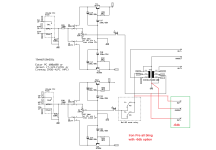
you'll have autoformer out of game, thus 6db less, if you remove jumpers and take outputs from pins No.1, so xformers just sleeping on pcbs
now, game is, you can even arrange second set of XLR outputs, call them -6db, wire them as attached, and still retain full XLR/RCA in-out converting functionality ......... xformers doing its job, and having two sets of outputs on disposal
mention this to Jim, so he can include this schm as tip, whenever time is for Build thread
edit: I can include pads for -6db outputs, for future ..... that's trivial work, routine fun while drinking first morning coffee
Attachments
Last edited:
🤦♂️Itsallinmyhead, thanks for your detailed response! So my DAC is the Perfect Wave, not direct stream.
Awesome!Heading down to visit 6L6 tomorrow so will report back.
You're very welcome. It's all the more impressive since it's your first. All I can say is, WOW!Thanks for your compliment regarding my build! After many rebuilds and mods this is actually my first diyAudio completed build!
Love the pics and the cool idea. I think a lot of people may follow in your footsteps.
It looks like the first part of your post because lost in virtual 🚀. If this works It world be fantastic ZM! I've ordered some more xlr sockets and switching things. Will hook up the -6 db when I Install switching. Looks like half the bounce off the b field? Would be cool to understand in general terms how this works from same wire. Possibly if some kids bounce in and other kids bounce out at different times there are no accidents? Peaceyou'll have autoformer out of game, thus 6db less, if you remove jumpers and take outputs from pins No.1, so xformers just sleeping on pcbs
now, game is, you can even arrange second set of XLR outputs, call them -6db, wire them as attached, and still retain full XLR/RCA in-out converting functionality ......... xformers doing its job, and having two sets of outputs on disposal
mention this to Jim, so he can include this schm as tip, whenever time is for Build thread
edit: I can include pads for -6db outputs, for future ..... that's trivial work, routine fun while drinking first morning coffee
It looks like the first part of your post because lost in virtual 🚀. If this works It world be fantastic ZM! I've ordered some more xlr sockets and switching things. Will hook up the -6 db when I Install switching. Looks like half the bounce off the b field? Would be cool to understand in general terms how this works from same wire. Possibly if some kids bounce in and other kids bounce out at different times there are no accidents? Peace
clarify what you want, what are your dilemmas and what I wrote unclear

so I can try to explain better
Zm, Sorry man thought -6db from your drawing option somehow magically had iron but clearly not. We are good. My issue was too much input voltage without pots. My DAC volume control wants more voltage to keep all the bits. So, I soldered some nice Vishay cf? Little blue guys as a voltage divider. 4.7k between CW and WIP and 4.99 between WIP and ground. Works perfectly and the world is wonderful! Thanks again for spending a morning with coffee figuring on my behalf... Peace
if you stare at schm I posted same as you're staring at Goats, it'll come to you

tip for "-6db" arrangement ( functionally 0db gain):
if you're using SE in to SE out, iron is not in game
If you're using Bal in to SE out, iron is not in game
if you're using Bal in to Bal out, iron is not in game
if you're using SE in to Bal out - iron is in game, producing negative phase from nuttin' and good vibes in air
Yes, indeed my friend! Staring, looking away for a spell, then more staring. The last line of your tips though was an aha clue though... Wonderful film! You are going too easy on me... oh and BTW thanks for the Borbely articles. Cheers
Hi, I don't see the 200$ variant, is there an image?I advise using Slagle's 200$ set, simply because I did tried those ( and other Slagle products which I also tried, including most expensive- most having slightly different arrangement of taps so least expensive ones being suitable if desired connection with gain)
No reason that any other quality AVC can't be used
yup, go for it, buy package from Store ( bargain) save Cinemags for some other purpose
buffers are set to have 100K Rin, matter of resistor value shunting input gate to GND
ZM,
Were you referring to R27 and R28?
In the schematic below these resistors have a value of 220K!

mea culpa, but not maxima
yeah, R27, R28
what counts is that you know which resistors are setting Rin, put values which suits you
yeah, R27, R28
what counts is that you know which resistors are setting Rin, put values which suits you
10K would be my choice, considering that today sources are mostly having decent low Rout
now, if you're going for higher value for vol pot, increase said input resistors to 220K or 270K
ZM,
If I go for a 10K pot, is it advisable to use 100K as Rin, rather than 220K?
yeah, sort of best compromise
pot of 10K is presenting generator/source with Rout of 2K5, in worst position, hich is exactly 50% of attenuation
I would rather see 100* that as load of next stage, but then you have to deal with interconnects capacitance, being more critical with greater Rin
as nobody around seems having same amount of OCD as I'm having (or none at all), just go with 100K set for buffer Rin
I marked these resistors as 220K, but what's more important is that I wrote several times about exact issue, besides dozen or more times Pa covered it, and several Greedy Boyz too
we are here for that, asking and getting answers or at least opinions, for any type of dilemma
Done!ZM's Thumb of rule - eyeball ( good enough) calculus for cathode follower Rout is 1/S, where you'll find S value in datasheets [ma/V] ....... right way should be deriving actual values from exact working point, but datasheet read is good enough in most cases
for 12AX7 (blasphemy using 12AX7 for that role but, hey, that' Tim de P. - he can do anything and I'm just going to green) S is 1.5mA/V so Rout is ~ 670R
in ZM's book - better to leave 50K volume and alter Rin of your Iron Pre to 270K
take care of not too long interconnect cables and that's it
Thanks ZM

Attachments
- Home
- Amplifiers
- Pass Labs
- What's wrong with the kiss, boy?