There is no specific timing for completion. I know that the author was working on it yesterday.
In the interim, feel free to ask any questions here or here in the 'Interest' thread.
Briefly...here is the way I've done a few of them. There are no gotchas, but I hope it's useful.
Stuffing the boards is straight forward. Given the parts density, you likely won't find yourself 'stuck' anywhere, but it is still wise to stuff parts from lowest (resistors and diodes etc.) to highest (caps, MOSFETs, transformers, relays etc). A few small tips off the top of my head. None of the parts require what I'd consider excessive heat or time to make a proper joint. Always inspect closely for bridges. Nothing special.
This happens after: the boards are stuffed, the AC supply is verified and connected properly, you're at full mains voltage with no dim bulb in place, and there has been no release of magic smoke.
The stuffing of the Twister board, connecting the 14-pin cable, connecting your choice of volume control, I/O, and chassis installation should be straight forward. There are a ton of pictures and advice from ZM if you're unsure. With the exception of plugging in the 14-pin cable(s) it's the same as any other pre-amp. If you're still unsure, ask. In addition, if you don't know how to set your Lorlin switch for the right number of "clicks" after reading the spec sheet / running a search, just ask.
Edited to add - For the Twister board, just in case it is not clear. For SE, the 14-pin header goes on the side with the LEDs if you happen to want to use LEDs for input indication.
Verify that the input selection works.
Put some music through it and run whatever tests you may like.
Do your own version of the happy dance.

In the interim, feel free to ask any questions here or here in the 'Interest' thread.
Briefly...here is the way I've done a few of them. There are no gotchas, but I hope it's useful.
Stuffing the boards is straight forward. Given the parts density, you likely won't find yourself 'stuck' anywhere, but it is still wise to stuff parts from lowest (resistors and diodes etc.) to highest (caps, MOSFETs, transformers, relays etc). A few small tips off the top of my head. None of the parts require what I'd consider excessive heat or time to make a proper joint. Always inspect closely for bridges. Nothing special.
- Overall for any build... I tick off and measure each and every part against the schematic. The schematic is the source of truth, but I use two other documents also. I use a spreadsheet for the parts list (provided) and the schematic (provided) along with the render of the board (provided). For each part, I test its value with an appropriate tester or at a bare minimum visually verify it against the schematic and parts lists. I make sure the three match. If so, I put a red tick next to them on the parts list and schematic. Once I install the part(s), I tick the board render and make the tick on the spreadsheet and schematic into an X. When I've cleaned and inspected the joints and verified orientation (as applicable) for the parts, I turn the tick on the board render into an X. That may seem like overkill to some, but if you do it that way... and the documents are correct, and you actually inspect the joints... it's highly unlikely that you'll have any issues.
If you find yourself with a question, ask. Most, if not all, of the kinks should be worked out by now.
- Ensure the proper placement and orientation of the JFETs and other TO-92 parts. See above. If you bought a kit, at a bare minimum verify the markings using magnification and sort them properly. I always recommend measuring with one of the little Mega 328 testers or similar.
- Don't forget to use a piece of wire or 0 ohm resistor for J5 (on 2023 boards) unless you're using another logic solution for input switching. This jumper never needs to be removed after the choice has been made, so I've never installed a pin jumper; just wire. Leave the rest of the jumpers uncapped for now.
- None of the parts requiring heatsinks require electrical isolation etc., if you purchased the recommended parts (or got a kit).
- If you're using a toroid, placement for a snubber circuit is provided, but not necessary. If you're unsure, just leave it out. You can always install it later for a fun A/B comparison. Note, if you have '2021' boards, do not install the snubber circuit.
- For balanced kits only, stuff the diodes with a DI notation if you're going to use that input as SE only. For any inputs used as SE, create a bridge between the appropriate (-) and (GND) pads for that input. It's also wise to make both channels match.
This happens after: the boards are stuffed, the AC supply is verified and connected properly, you're at full mains voltage with no dim bulb in place, and there has been no release of magic smoke.
- Set V+ and V- (DC Voltage)
Adjust P1 and P2 for each board until V+ is +15V0 and V- is -15V0
GND, V+ and V- pads are clearly marked on PCBs.
Do not move forward if you cannot adjust the voltages to within 0V1 or if the voltage seems unstable.
- Null DC offset (DC Voltage)
- SE
- No jumper caps in place for JP1 or JP2
- Measure at center pin of JP1 and at the center pin JP2 NOT between those two pins*
- Turn P3 / P4 respectively until voltage shows 0V +- 5mV
- Cap the jumpers for your choice of gain.
- Balanced
- No jumper caps on JP+ or JP-
- Measure at pin 1 of JP+ and pin 1 of JP- NOT between those two pins*
- Turn P3 / P4 respectively until voltage shows 0V +- 5mV
- Cap the jumpers.
- SE
Do not move forward if you cannot null the offsets to less than +- 5mV
* Measure between the appropriate pin and GND.
The stuffing of the Twister board, connecting the 14-pin cable, connecting your choice of volume control, I/O, and chassis installation should be straight forward. There are a ton of pictures and advice from ZM if you're unsure. With the exception of plugging in the 14-pin cable(s) it's the same as any other pre-amp. If you're still unsure, ask. In addition, if you don't know how to set your Lorlin switch for the right number of "clicks" after reading the spec sheet / running a search, just ask.
Edited to add - For the Twister board, just in case it is not clear. For SE, the 14-pin header goes on the side with the LEDs if you happen to want to use LEDs for input indication.
Verify that the input selection works.
Put some music through it and run whatever tests you may like.
Do your own version of the happy dance.
Last edited:

Thanks for the helpful information. Can't wait to get started!
IAIMH
is offset adjusted to +5/-5mv an acceptable range for this circuit?
Nice write up. Thanks. nash
is offset adjusted to +5/-5mv an acceptable range for this circuit?
Nice write up. Thanks. nash
Hi Nash,Null DC offset (DC Voltage)
Do not move forward if you cannot null the offsets to less than +- 5mV
- SE
- No jumper caps in place for JP1 or JP2
- Measure at center pin of JP1 and at the center pin JP2 NOT between those two pins*
- Turn P3 / P4 respectively until voltage shows 0V +- 5mV
- Cap the jumpers for your choice of gain.
- Balanced
- No jumper caps on JP+ or JP-
- Measure at pin 1 of JP+ and pin 1 of JP- NOT between those two pins*
- Turn P3 / P4 respectively until voltage shows 0V +- 5mV
- Cap the jumpers.
Any time. I'm glad it helps. See above in bold red for emphasis.
tl;dr - Yep. Good to go. 😉
Hope it's fired up and making beautiful music soon!
^ Definitely on all of mine. I was down as low as my handheld meters would go. +-5mV was the original guidance. Should I bump it lower? +- 1mV? Happy to revise as needed.
@nashbap - I don't want to cause any confusion. I may have misinterpreted what you were asking. If you were asking... Should we try for lower, then that is definitely a question for the mighty one directly. 🙂
@nashbap - I don't want to cause any confusion. I may have misinterpreted what you were asking. If you were asking... Should we try for lower, then that is definitely a question for the mighty one directly. 🙂
I dont see any problem getting and keeping offset under+/- 0.25mv. I was just a bit surprised by the +/-5mv recommendation which I thought was high. No big deal.
Thank you. nash
Thank you. nash
I am close to finishing my balanced Iron preamp but waiting on remaining parts, I had a couple questions to ask.
- I looked everywhere but could not find out what the purpose of JP- and JP+. I see the jumper needs to be removed during dc offset/voltage but scanning the thread everyone's builds include them connected together.
- Is everyone with balanced using 3 total fuses? One master, and one for each toroidal (channel)?
both SE and Balanced - jumpers need to stay open/removed to the moment when DC Offset of buffers is set to 0mV (as close you can get)
then you put them in place for first time
besides that, with SE, you can choose +6db or +12db gain with jumper position
simple as that
now - donut fuses - feel free to use just one, common for both of them ; value of fuse for both is so small that it'll pop whatever happens
so, one IEC, one fuse and one mains switch - no need to complicate when there is no any benefit
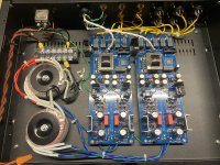
you didn't think of maximizing distance between mains wires & Donuts - to channel pcbs?
first most left possible, second most right possible?
it always pays off
first most left possible, second most right possible?
it always pays off
Can you elaborate or recommend how I should change the layout? I tried something similar to another build I saw here.you didn't think of maximizing distance between mains wires & Donuts - to channel pcbs?
first most left possible, second most right possible?
it always pays off
move Donuts all the way left, keep mains wires also left, tight twisted
move channel pcbs all the way right
I suppose volume pots are at front plate, so no worry about them situated back, with pcbs
move channel pcbs all the way right
I suppose volume pots are at front plate, so no worry about them situated back, with pcbs
In addition to what ZM said, I would suggest stacking the toroids if the case is tall enough, locate them at the left front so that they are far away from the audio signals and signal transformers. Also locate the AC connector block to the left side of the case. Finally, rotate the toroids for minimum noise. My experience with toroids is that they leak EMI at the wire locations, so the best orientation is with the transformer wires lined up facing the front and back of the case. That also keeps them away from the PCBs.
Is it possible to buy bal PCB?
If you ask in https://www.diyaudio.com/community/...ya-store-register-your-interest.390509/latest , I believe IAIMH will reply to you , confirming something as "soon"
He's The Guy in Trenches
Thanks to all for this thread. I have a 2021 board, stuffed, and an Italian chassis. I am waiting for mouser to ship the back-ordered selector switch before finishing up.
my only need is to find an ac socket for the Italian chassis, the opening is around 28 by 47 mm…couldn’t seem to find a part # in the thread or the proper part from digikey.
thanks, if you can furnish a part number.
Dean
my only need is to find an ac socket for the Italian chassis, the opening is around 28 by 47 mm…couldn’t seem to find a part # in the thread or the proper part from digikey.
thanks, if you can furnish a part number.
Dean
- Home
- Amplifiers
- Pass Labs
- What's wrong with the kiss, boy?