![20230316_180357[1].jpg](https://www.diyaudio.com/community/data/attachments/1062/1062259-9776c0c7ff3c2a9f7345bc10a92b63f4.jpg?hash=l3bAx_88Kp "20230316_180357[1].jpg")
I did a low noise pre amplifier with 16 CPH3910 FETs in parallel where I wanted
to avoid negative feedback in the usual way around FETs- Cascode-opamp-
source of FETs. That develops negative input resistance if you want just a little
bit more than audio bandwidth.
But I needed somewhat defined gain. Gain of the FET stage is proportional
to the square root of drain current, so I force-fed the source from a current
mirror. Unluckily, this is now a very high impedance node. So I used a few 1000uF
of electrolytics to ground it for AC.
It turned out that you can see every electron that defects through the electrolytics.
That creates a lower 1/f corner where the noise rises from brodband 340 pv/rtHz
towards lower frequencies. Oh, if it was only 1/f !!! It is more like 1/f**3, at decade
below the corner, the noise is already 30 dB worse.
Oscons were worst by far. The corner frequency was abt. 1 KHz and with 1/f**3
rise you get FFT analyzer overflow at 10 Hz. Unusable as an amplifier.
Nippon Chemical Alu was better than the Oscons by more than an decade:
100 Hz corner IIRC, but the same rate of rise.
AVX wet slug tantalum 4700uF/25V was better by another decade, but €100
a pop will prohibit widespread use. Corner was at 10 HZ, borderline usable
with a 3rd order high pass at 10 Hz.
I wanted an amplifier but what I got was a circuit to compare the leakiness
of electrolytics. 1/2 :-(
OffTopic for this thread:
FETs have 2 TCs, a positive and a negative one. At the right current they
cancel. For 16 CPH3910 they cancel at 45 mA total, at least in simulation.
There is not much gain change between 20 and 60 degrees centigrade.
The new TI parts seem to cancel near Idss, much too high at current
energy prices. CPH3910 - A way to a better solution. Fits where BF862 did.
Gerhard
Last edited:
And as you ask about the UKL, I put a couple in a new order from Mouser, when they arrive I will let you know the test results.
It would be fantastic, thank you! People report that UKL sound good in the signal path, although a little dry compared to UKZ. In our case they are nowhere near the signal path, so hopefully OK.
Don’t hold your breath expecting much from UKZ capacitors. They have larger than average leakage. Here are some leakage measurements. All capacitors were measured after 5 minutes with 6.8 V applied. As leakage is proportional to capacitance, and capacitors had different values, normalized value for leakage per 100 uF was calculated.
I’m using now in my super regulator builds only EEH-AZA hybrid polymer capacitors as they are triple L - low ESR, low leakage and long service life.
- Nichicon UKZ 33 uF/50V – 28 nA (84 nA)
- Panasonic EEU-FM 330 uF/35V – 25 nA (7.6 nA)
- Panasonic EEU-FM 220 uF/35V – 12 nA (5.5 nA)
- Panasonic EEH-AZA 150 uF/25V – 4 nA (2.7 nA)
- Panasonic EEH-AZA 330 uF/35V – 7 nA (2.1 nA)
I’m using now in my super regulator builds only EEH-AZA hybrid polymer capacitors as they are triple L - low ESR, low leakage and long service life.
Attachments

I’m using now in my super regulator builds only EEH-AZA hybrid polymer capacitors as they are triple L - low ESR, low leakage and long service life.
This is a great information, thanks! Can you please spell out for those of us less advanced, in which positions do you use these caps? Is it C9/C10 or also C3/C7? What is the value of R4/R11 and the value of the caps in your build? (I see the test values on the charts, but which did you choose for the actual build?) Did you change any other resistors or capacitors? Finally, have you tried to see if this makes any audible difference? Thanks again!
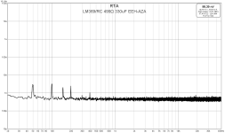
PS. It looks like with EEH-AZA 330 uF you get more noise with a higher resistance. Is the difference perhaps due to the resistor noise?
Last edited:
No, at least not directly. The higher resistance produces more voltage noise
but at the same time it lowers the corner frequency where the filtering starts
to work. There is nothing wrong with 22Meg/10uF foil at the input of a
FET amplifier.
The constant current source / mirror in my amplifier was an even
higher source resistance that acted like a magnifying glass for the leakage
current of the electrolytic capacitors.
In retrospect, I could have weakened the current source (--> lower Z) and
not throw it out of the window completely. If the FET source current varies
a % that does no real harm to the gain.
The capacitors seem to be in short supply. DK has not all the values
available. Get them while you can.
< https://www.digikey.de/de/products/...en/69?s=N4IgTCBcDaIDoBcAEBRFAJAtAQQFrZAF0BfIA >
( I would be interested in the actual RC values of the LM339 filtering.)
Gerhard
Last edited:
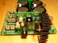
I’m using those capacitors for every position, but my voltage regulators are different, though they are still super regulators based on Jung-Didden essential design principles (picture attached).Can you please spell out for those of us less advanced, in which positions do you use these caps?
For the original design, they can be recommended for voltage reference filtering (C9, C10). They could be good for C4, C8 and all other positions as well, but someone else will have to check that.
For my actual builds, I used 330 uF and 150 uF values with 1 kΩ resistor (different builds).
It is not likely that PS voltage reference changes would change sound of preamplifier or amplifier. This is not a DAC where voltage reference has direct impact on sound. I don’t hear sound changes after changing a single capacitor, short piece of wire, type of metal plating in opamp socket, etc. So, I’m not qualified to comment on that. 🙂Finally, have you tried to see if this makes any audible difference
However, I do hear sound changes going from CRC to super regulator PS. 😀
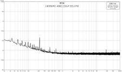
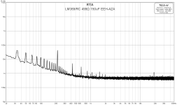
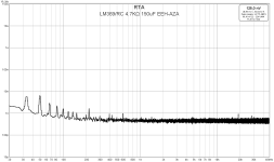
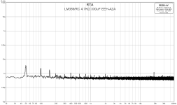
When measuring such low voltages in the several nV range, environment noise (EMI) can vary results in consecutive measurements. To measure actual LM 329 filtered noise instead of environment induced noise, I had to switch off any AC power in vicinity and especially all switching power supplies and LED lighting. Battery supply for DUT was used as well.It looks like with EEH-AZA 330 uF you get more noise with a higher resistance. Is the difference perhaps due to the resistor noise?
Attachments
Last edited:
Measurements were performed on breadboard assembly with RC values as specified. In my actual regulators 1 kΩ with 150/330 uF is used as good enough for noise and with acceptable time constant, so nominal output voltage is achieved in less than 2 seconds.I would be interested in the actual RC values of the LM339 filtering.
It is worth to mention that those polymer capacitors seem to need a little more time to drop initial high leakage values than the ordinary electrolytics.
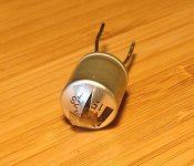
Yesterday, I discovered another good property of EEH-AZA capacitors. They explode gracefully with no smell, spill or smoke. 🤣
One 330 uF capacitor was borrowed from another breadboard circuit on the bench. I managed to return it reverse connected. After some time, I was greeted with very loud and sharp crack.
Attachments
Oh, I had that a month ago on a home-etched SMD board without
overlay print. When I populated it, I reversed one at the input side
of an LT3042. It survived about for a minute and decided to explode
when I had it under the stereo microscope. Visually in Cinemascope
and 10 mm before my eyes. Quite shocking.
overlay print. When I populated it, I reversed one at the input side
of an LT3042. It survived about for a minute and decided to explode
when I had it under the stereo microscope. Visually in Cinemascope
and 10 mm before my eyes. Quite shocking.
I used a battery fed Super Regulator as the power supply for the USB input of my DAC (Aqua La Scala with Telefunken ECC801S) and it made a dramatic difference in sound.It is not likely that PS voltage reference changes would change sound of preamplifier or amplifier. This is not a DAC where voltage reference has direct impact on sound.
Then one day I accidentally reversed the polarity of the battery. The regulator fried and the input capacitor (Elna Silmic 2) exploded, but without a sound or smell. So now I am building a new regulator.
Thanks for you insights!
What is the brand/model of the heatsink that you use for that 480A MOSFET? Thanks again!my voltage regulators are different, though they are still super regulators based on Jung-Didden essential design principles (picture attached).
Hi,Don’t hold your breath expecting much from UKZ capacitors. They have larger than average leakage. Here are some leakage measurements. All capacitors were measured after 5 minutes with 6.8 V applied. As leakage is proportional to capacitance, and capacitors had different values, normalized value for leakage per 100 uF was calculated.
Attached are noise measurements of RC filtered LM329 voltage reference. LNA used for measurements has noise floor at 0.445 nV/rtHz.
- Nichicon UKZ 33 uF/50V – 28 nA (84 nA)
- Panasonic EEU-FM 330 uF/35V – 25 nA (7.6 nA)
- Panasonic EEU-FM 220 uF/35V – 12 nA (5.5 nA)
- Panasonic EEH-AZA 150 uF/25V – 4 nA (2.7 nA)
- Panasonic EEH-AZA 330 uF/35V – 7 nA (2.1 nA)
I’m using now in my super regulator builds only EEH-AZA hybrid polymer capacitors as they are triple L - low ESR, low leakage and long service life.
I have checked the specsheet of the AZA range and could not find the Panasonic EEH-AZA 330 uF/35V – 7 nA (2.1 nA). Can this cap be from a different serie?
Thanx, Ruthless
You are ruthlessly correct (pun intended). 😀
There is no 330uF/35V in the EEH-AZA series. It was 330uF/25V.
Another typo is LM369 specified on the noise measurements, while it was LM329.
There is no 330uF/35V in the EEH-AZA series. It was 330uF/25V.
Another typo is LM369 specified on the noise measurements, while it was LM329.
Thnx for your clarification.You are ruthlessly correct (pun intended). 😀
There is no 330uF/35V in the EEH-AZA series. It was 330uF/25V.
Another typo is LM369 specified on the noise measurements, while it was LM329.
I noticed on your board, see picture #3087 that you are using a 35V/330uF EEH-AZS cap. Did you test this cap as well and how does it perform compared to the 25V/330uF EEH-AZA?
Regards, Ruthless
I went to workshop to check and it was 330uF/35V EEH-AZS after all. 🤦♂️
Comparing results of 150uF/25V EEH-AZA and 330uF/35V EEH-AZS, it is evident that their leakage is practically the same.
More important fact is that many recent production capacitors will exceed requirements for a low leakage capacitor in voltage reference low pass filter, explained in the Walt Jung’s article: An_Improved_Reference_Filter_for_Audio_Regulators.pdf
Just look at the Panasonic FM series results,
When checking capacitors for actual leakage, it is good to put some working hours on them. Fresh out of bag, they will have several times higher leakage than after being under voltage for a day. In example, after leaving UKZ capacitors under voltage for the whole day, their leakage dropped to 25 nA per 100 uF.
So, without much headache in finding components, we can use 150 uF/4.7 kΩ RC filter in the super regulator. However, that will result in slowly ramping regulator output voltage, requiring some 3 seconds to reach 95% of nominal output voltage.
Hello Tombo56,
Thank you for your additional information and link to Walt Jung’s article. All clear now and I will make a sample with both capacitors as advised.
I have a question about a specific capacitor that I would like to have tested. Please let me know in a PM if this is an option for you.
Have a nice evening.
Regards, Ruthless
Last edited:

You can do whatever you wish. You can even slave one of the regulators to the other, and thereby create a "dual TRACKING regulator". If that's what you wish.
- Home
- The diyAudio Store
- Super Regulator