Well the original Gamut is built like that and it works like a charm. Accuphase use a copper bus bar for the central star ground of their amp. Just a piece of copper instead of a piece of copper wire. Same principle…
SB
SB
It is completely sufficient to have a star point and then connect it to the electrolytic capacitor ground via a connection.
Hello Gents,...just ordered the 2 x 500VA / 2 x 42 transformer with Toroidy. I didn't order the suprems but the normal audio grade ones. If I'm looking at the drawing (i know its not on scale) and I'll be needing 2 caps per rail so 8 caps in total. If I would choose the PSU V3.0...I wonder whether that would all fit on the base-plate or migth it be better to use baseplate mounted caps....or the fornt panel for that matter....

regards
Willem
regards
Willem
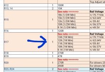
How urgent is a replacement here? Is it like "replace now" or more like "replace occasionally, if at all..."?We changed R17 to 1 watt in the latest BOM (s). Andy reported that the 0.5W resistor was getting warm, in that position.

Three quick questions as I near completion on my first Wolverine:
1)The Q104 holes at the edge of the board are not connected to anything. Was the intention to allow for a Q104 mount on the heat sink closer to an output transistor, connected with wires to the "normal" position on the board?
2)What is the "socket head only" warning on the bottom right mounting hole? I know about different types of screws, but is this simply meant to tell me not to use a spacer with the male thread up through the board to ensure clearance to the ring terminals?
3) D9 on the IPS in the VAS emitter follower forces a DC mismatch on the mirror collectors. I'm used to seeing this circuit with just an emitter resistor and also tied to gnd, allowing the mirror helper and VAS to force near equal mirror collectors. I can see the advantage of this lower Q12 Vce allowing use of the low-noise/low-voltage transistor, but I'm unclear about the diode's purpose.
Thanks.
One comment on the board nearing completion. The lead spacing for R101, R104 is a mm or so short of a good fit for standard 1/2W metal film resistors. The CFMs fit okay, but I have a large collection of less esoteric parts, and am sure others may as well. That might get fixed if there is another purchase in the works.
60V and 5 mA makes 0.3 Watt. However the schematic mentions 1 Watt and the BOM even 2 Watt. 😵How urgent is a replacement here? Is it like "replace now" or more like "replace occasionally, if at all..."?
As mentioned above, it was reported that resistor R17 becomes warm, obviously still within spec. It was decided to replace it with a 1 watt type, for new builds.
To assist builders find parts, that are currently in stock at Mouser, the BOM lists 1W and 2W types (that you failed to mention above).😵
To assist builders find parts, that are currently in stock at Mouser, the BOM lists 1W and 2W types (that you failed to mention above).😵
I've built 14 boards to date and have had zero issues with r101 or r104 being to small using both MBB and CFM resistors from the BOM. I guess if you go outside the BOM for parts there could be a fitment issue but I don't see why there would be a need for that.One comment on the board nearing completion. The lead spacing for R101, R104 is a mm or so short of a good fit for standard 1/2W metal film resistors. The CFMs fit okay, but I have a large collection of less esoteric parts, and am sure others may as well. That might get fixed if there is another purchase in the works.
Answering question 3)Three quick questions as I near completion on my first Wolverine:
1)The Q104 holes at the edge of the board are not connected to anything. Was the intention to allow for a Q104 mount on the heat sink closer to an output transistor, connected with wires to the "normal" position on the board?
2)What is the "socket head only" warning on the bottom right mounting hole? I know about different types of screws, but is this simply meant to tell me not to use a spacer with the male thread up through the board to ensure clearance to the ring terminals?
3) D9 on the IPS in the VAS emitter follower forces a DC mismatch on the mirror collectors. I'm used to seeing this circuit with just an emitter resistor and also tied to gnd, allowing the mirror helper and VAS to force near equal mirror collectors. I can see the advantage of this lower Q12 Vce allowing use of the low-noise/low-voltage transistor, but I'm unclear about the diode's purpose.
Thanks.
D8, Q12(when saturated), and D9 forms a Baker Clamp on Q13 when the VAS is clipping on the negative half cycle. As far as causing voltage difference on the collectors of the current mirror transistors I'll have to double check sim. The current through both mirror transistors will be the same.
Jeremy
As mentioned above, it was reported that resistor R17 becomes warm, obviously still within spec. It was decided to replace it with a 1 watt type, for new builds.
To assist builders find parts, that are currently in stock at Mouser, the BOM lists 1W and 2W types (that you failed to mention above).😵
No failure here, must have been someone else who failed.
@fireanimal I will readily admit to not getting everything off of the BOM, since I have rather large stocks of equivalent parts. R111A/B are 12 mm, and 101/104 are only 10 mm. Looking at the board, there does not seem to be a good reason for the difference. The 1/2 watt resistors I have do vary a bit depending on who I got them from and when. Turns out that the 1k that were available when I bought these are a bit larger than some others, but by no means an isolated size difference.
It's just an observation. Feel free to ignore it.
It's just an observation. Feel free to ignore it.
@mhuth1776 those cannot be made larger anyhow if you look closely at the traces due to creepage the lead spacing is as large as possible.
My comment was not meant in a negative way towards you but to simply guide others and future builders that there isn't an issue if you use BOM parts.
My comment was not meant in a negative way towards you but to simply guide others and future builders that there isn't an issue if you use BOM parts.
@OmeEd let's not make this into a big thing and derail this awesome thread please. No one failed I think this is just a misunderstanding is all. The original 1/2watt part was spec'd correctly and is within its limits. Since there was extra space there I recommended changing to a 1 watt for future builds. There is also enough space for some 2 watt parts to fit but not because it's needed it is just an option so it's easier to source parts if others aren't available.
Long story short. 1/2 watt fine 1 watt fine 2 watt fine use what you have or can source and enjoy this great amplifier and build thread!
Long story short. 1/2 watt fine 1 watt fine 2 watt fine use what you have or can source and enjoy this great amplifier and build thread!
Settle down @OmeEd you using and old bom. Please download the latest version from the link I sent you.
We are trying to help you guys out as much as we can and these types of comments show no appreciation for the effort that has been put in.
Attachments
I just play the card someone else called. You both need to re-address your grief. The cited BOM is 24 jan 23.
Latest BOM is 27 Jan 23The cited BOM is 24 jan 23
- Home
- Amplifiers
- Solid State
- DIY Class A/B Amp The "Wolverine" build thread