I don't put zip files in the Dropbox.The file: 1st GB Updated BOM 2023 Jan 24.xlsx
Packed in the zipfile "DiyAudio Members - Wolverine Project.zip" was downloaded 24-02-2023 11:23 CET
This must have happened when you downloaded it. Please move on @OmeEd
You know @OmeEd most people that ask questions or find issues ask questions and when they are answered say thanks or give the post a like. Maybe you should consider doing the same for the people that are trying to help you. Also monitor your own posts for likes. If you don't get any maybe that's saying something about the way you are contributing to this thread.

Why are you behaving like this Stuart, it's not friendly at all. And yes, you should have moved on, but you did not.
I just checked the dropbox, and the mentioned file 1st GB Updated BOM 2023 Jan 24.xlsx is still there.
So your assumption that I have an old file is misplaced.
The zipping happens when you press the dropbox [download] button, then everything gets zipped up. Easy as pie.

I just checked the dropbox, and the mentioned file 1st GB Updated BOM 2023 Jan 24.xlsx is still there.
So your assumption that I have an old file is misplaced.
The zipping happens when you press the dropbox [download] button, then everything gets zipped up. Easy as pie.
Honestly can we just move on. This petty behavior is pointless and unnecessary.
I’ve been Reading Randy Sloan’s amp book and it has been quite helpful.
I am curious what the cap multiplier is doing?
I am curious what the cap multiplier is doing?
It's you that is posting and arguing over a trivial point. You know very well that 0.5, 1W or 2W may be used in that position without an issue.
However if you have designed a better amp please post the link.
However if you have designed a better amp please post the link.
A cleaner supply to the front end.I’ve been Reading Randy Sloan’s amp book and it has been quite helpful.
I am curious what the cap multiplier is doing?
Well I agree to this, but look what just happened above. While a polite "sorry, ......." would have been so much better.Honestly can we just move on. This petty behavior is pointless and unnecessary.
Maybe a good moment to answer a stupid question from a noob where everybody can laugh about after a good night sleep....
https://www.diyaudio.com/community/...he-wolverine-build-thread.385920/post-7281980
https://www.diyaudio.com/community/...he-wolverine-build-thread.385920/post-7281980
Three quick questions as I near completion on my first Wolverine:
1)The Q104 holes at the edge of the board are not connected to anything. Was the intention to allow for a Q104 mount on the heat sink closer to an output transistor, connected with wires to the "normal" position on the board?
2)What is the "socket head only" warning on the bottom right mounting hole? I know about different types of screws, but is this simply meant to tell me not to use a spacer with the male thread up through the board to ensure clearance to the ring terminals?
3) D9 on the IPS in the VAS emitter follower forces a DC mismatch on the mirror collectors. I'm used to seeing this circuit with just an emitter resistor and also tied to gnd, allowing the mirror helper and VAS to force near equal mirror collectors. I can see the advantage of this lower Q12 Vce allowing use of the low-noise/low-voltage transistor, but I'm unclear about the diode's purpose.
Thanks.
Hi mhuth,
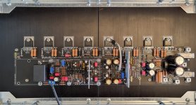
1, Q104 holes on the edge of the board are for mounting similar to honey badger for Q104, I used small leads to connect Q104 and it is attached to the top of Q110 with a tiny bit of thermal paste in between. the leads connect closer to the center of the board near the screw hole and marking "VBE" see photo below
2, Socket head cap screws have a smaller diameter than pan head screws and yes the reason is creepage and clearance distance from the output terminal.
3, I will have to defer to JJS/StuartMP on this one.
Hope this helps
-Dan
Attachments
Last edited:
It's hard to answer your question as some people have preferences when they populate the chassis.Maybe a good moment to answer a stupid question from a noob where everybody can laugh about after a good night sleep....
https://www.diyaudio.com/community/...he-wolverine-build-thread.385920/post-7281980
I put the transformers near the front panel away from the input stage and away from the speaker cable. That doesn't mean you cannot have a different configuration.
I also use two diode bridges per channel.
Look at some of the photos that were posted for inspiration.
Thx Harry,.... yeah I did a lot of reading and looking. Its really amazing what you guys have been doing. Once I get the goodies I will test place the larger components taking into account your notes. I'll be using the 2 bridges per channel as well with no psu ground to the reservoir caps.
w.
w.
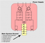
You still have to connect somehow + pole in the negative branch and the - pole in the positive branch of the reservoir caps to PSU ground. It'll make the 0V.
This is the drawing from stuarts album I was looking at. I just have to make sure to verify the polarity of both secondary windings.
Attachments
Last edited:
@marktd Q12 and Q13 comprise the voltage amplifier stage, usually called VAS for short. Q12 reduces the load on the input stage, and Q13 collector has the drive voltage for the output stage. It's loaded by a current source, Q10 and Q11. Sloan, Self, and Cordell all cover power amplifier architecture. You will find similar circuits in each of these tomes. Note that this is rather advanced compared to the "teaching" circuits presented in the books. However, the advanced part of Self or Cordell begins to get into the issues addressed by this particular circuit.
Thanks. I’m most of the way through the Sloan book, which has been helpful. I’m stretched financially after a move and business slowdown, or I’d buy Cordell and Self. Right now I’m slowly gathering parts for this.
Thanks @fireanimal for the technical details. I appreciate those sorts of answers. I have 50 years in electronics, but always on the digital side of things where ever smaller and lower voltage were the rule. I'd heard the term creepage, but never had to deal with it before, as everything I did was 5 volts and under and the main limitations have been feature size related to PCB vendor's capabilities. (That and transmission lines and signal delay 😎.
- Home
- Amplifiers
- Solid State
- DIY Class A/B Amp The "Wolverine" build thread