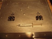
While searching for a physical drawing of the THF-51 I found the attached PDF which is quite fun (in itself) that a tube tester can be used for testing the SIT.
Most important I found the distance between the two holes (43.3 mm) from center to center.
From previous discussion here I learned that M4 thread should be cut into the heatsinks and not the alu panels which would have been the easy solution.
For the PCB mount however threads will be cut into the panels. Probably M3 threads.
I need to look more into the puck MOSFET......probably same solution there for mounting this device as for the SIT.
I will place the big devices a little bit below horizontal centerline to get the best cooling performans from the heatsinks.
Attachments
1/3 of heatsink height is best scenario
now, threads .... do not over-engineer that - as long you have enough threads, who cares are they just through top plate or all the way?
now, my eyeball estimation is that 5mm length of M4 in decent Al is more than enough for necessary torque
go figure
now, threads .... do not over-engineer that - as long you have enough threads, who cares are they just through top plate or all the way?
now, my eyeball estimation is that 5mm length of M4 in decent Al is more than enough for necessary torque
go figure
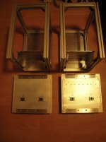
Ok, this will make it a lot easier. The panel is 10mm and I can make through hole threads in those panels.
Maybe the heatsink aluminium is a little bit harder than the panel aluminium...judged after I have drilled in both.....but not 100% sure about that.
I don't see many placing the power transistors "offset" (closer to the bottom) at the heatsinks.......most will just center.......at least the constructions I have seen here (by memory). By eye-catch I think even my VFET amp the bracket is placed closer to the top.
I make sense to place it lower as the hot air will go up.
don't make me search for reference articles
but yes, for your situation and for any situation where (any number of) outputs are in one line, 1/3 from bottom is optimal height
but yes, for your situation and for any situation where (any number of) outputs are in one line, 1/3 from bottom is optimal height
Hello,
when I built my monoblocks with IXYS- Mosfets, I used the 1/3 to 2/3-rule for the height of the Mosfets on the heatsink.
Horizontally - or from left to right- I made it 1/4 - 2/4 (betweeen the 2 Mosfets) - 1/4 (to the edge of the heatsink).
But however you want to do it - as long as it stays in the expected thermal region - all is good.
Cheers
Dirk 🙂
Attachments

we can't count on your build
whatever you say, we don't know is it looked at from Beaver or Hawk perspective

whatever you say, we don't know is it looked at from Beaver or Hawk perspective
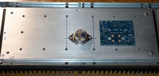
I have marked the holes for SIT and PCB on both SIT panels and I am ready to drill / cut threads........
I just have to remember not to drill 3mm / 4mm but a little smaller diameter....... for the M3 / M4 threads.
It would be a bad mistake to make.......
I just have to remember not to drill 3mm / 4mm but a little smaller diameter....... for the M3 / M4 threads.
It would be a bad mistake to make.......
Attachments
Yep! I can understand. Nothing mentioned on those pics where North- South or East-West is...
And I don't know if I should look at this from the Beaver- or Hawk- perspective... 👀
greets from
Dirk
And I don't know if I should look at this from the Beaver- or Hawk- perspective... 👀
greets from
Dirk
Hello Meper,
for M3 - center hole has a diameter of 2.5 mm, for M4 - center hole is 3.3 mm.
Greets
Dirk
for M3 - center hole has a diameter of 2.5 mm, for M4 - center hole is 3.3 mm.
Greets
Dirk
Yes, I have those numbers in my table.
I have had success drilling 0.1mm less....so 2.4 and 3.2 for aluminium and when it is drilled free hand then holes tend to be just a little bit larger than when done using a bench drill.
I have had success drilling 0.1mm less....so 2.4 and 3.2 for aluminium and when it is drilled free hand then holes tend to be just a little bit larger than when done using a bench drill.
........
It would be a bad mistake to make.......
Yep! I can understand. Nothing mentioned on those pics where North- South or East-West is...
And I don't know if I should look at this from the Beaver- or Hawk- perspective... 👀
greets from
Dirk
where is that picture of you , standing upside-down on your amp(s) ?
I am searching for pic... Beaver is diving into sea of electrons and 1-0-0-1-0-1-0-0-0-1 informations...


🤣🤣🤣🤣🤣🤣Sorry, Meper! I don't want to crash your thread.
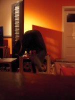
This is for Zen Mod: the 50W-SE-Schade-amp-hot-hands-bulletproof-test-upside-down
Don't do this at home!
Save the amps...
A "Crash-party" is always fun.
I wonder if Dirk can do the same exercise on top of the tall speakers.......some "Martin Logan" look alike?
Are they easy to drive?
I wonder if Dirk can do the same exercise on top of the tall speakers.......some "Martin Logan" look alike?
Are they easy to drive?
Hello Meper,
the ESLs are from the Netherlands: Audiostatic ES300R
https://www.audiostatic.com/
Much easier to drive than Logans. And better efficiency. My F5T-Monoblocks drive them with ease. Also the M2X can drive them pretty well.
But, as with most ESLs - don't let them work hard in the bass. Subwoofer helps ESLs a lot. And then they can play really loud.
My ones got new foils 5 or 6 years ago. Was a very good investment.
Cheers
Dirk
Ok so those ESLs are "full" panel speakers.......
The Logans I have listening to all had a normal woofer for the bas:
https://www.tonepublications.com/review/scaling-the-mighty-neolith/
They write something about a Xs300 .......which "smells" a bit like a Pass?
I did not know they could drive Logans 🙂
The Logans I have listening to all had a normal woofer for the bas:
https://www.tonepublications.com/review/scaling-the-mighty-neolith/
They write something about a Xs300 .......which "smells" a bit like a Pass?
I did not know they could drive Logans 🙂
- Home
- Amplifiers
- Pass Labs
- Lazy Singing Bush mono block build using THF51s