You got it, St. Peter(sburg). Desolder and pull one side of R10, test, resolder. Desolder and pull the other R10, test, report the results back to Mr. Pass via email.The pulsing is likely the power supply. Most probably you have 1 or 2 broken power transistors on one channel. You can test this by removing the power supply input resistors one at a time and seeing if the other channel works. Then email me your address for a replacement pair.
What does NP use for the ACA Mini board that ships from the store? 1oz or 2oz?I had some mono PCBs done and because I'm a noob at this, I didn't pay attention and got 1oz copper. Should I reorder with 2oz? Or does it not matter with mini?
OK, I took off the left power supply resistor. I noticed a spark when I connected the power power came on then went off, and now will not power on again. This was done with no input or output connections.
No idea. That's why I asked to begin with 🤷🏻♂️What does NP use for the ACA Mini board that ships from the store? 1oz or 2oz?
I did make my traces as wide as possible where I thought it mattered though.
I just did it again to retest it. I think it was actually the mechanical noise of putting in the connector, I Turned it on and it stayed on for a minute or so. The light ends up dimming on the power supply. Guessing its in protection.Where did you see the spark?
Morning Nelson I see your note. I tried to turn it on, but it just shuts off. Is the goal for me to try to play music through it before it shuts off? Or does the shutting off part send us down a different path. Thank You-Marc
@St. Peter(sburg) The ultimate goal is to play music, of course... right now, however, the goal it to get it to stay on.
Something is obviously wrong, so let’s see what we can see, would you please post a series of well-lit, in-focus photos here so the truobleshooting hive mind can start the debut process? Thanks.
Something is obviously wrong, so let’s see what we can see, would you please post a series of well-lit, in-focus photos here so the truobleshooting hive mind can start the debut process? Thanks.
@St. Peter(sburg)
When I understand you correctly: now you unsoldered R10 from one channel and it is still shutting down.
If this is correct, then try the other channel: resolder the first R10 and unsolder R10 from the other channel.
Does it also shut down?
When I understand you correctly: now you unsoldered R10 from one channel and it is still shutting down.
If this is correct, then try the other channel: resolder the first R10 and unsolder R10 from the other channel.
Does it also shut down?
The immediate goal is (I believe) to determine if one or both channels has a fault that is causing the circuit to draw too much current; damaged transistors from your earlier 'oops' as an example.Morning Nelson I see your note. I tried to turn it on, but it just shuts off. Is the goal for me to try to play music through it before it shuts off? Or does the shutting off part send us down a different path. Thank You-Marc
One of the advantages of PSUs of this type is that they will shut themselves down if they are overloaded. Your PSU seems to be doing this. So, a logical step would be to see if one channel and/or the other is causing this, and narrow it down further later.
By removing the PSU resistors (R10) from the circuit, one at a time, you effectively remove one channel at a time from the circuit to see if the PSU goes into protection mode or not.
1. Remove R10 from Channel A (lift one leg or remove it completely, your choice). See if PSU stays on.
2. If yes, then you know Channel A is the culprit. Stop.
3. If the PSU goes into protection. Replace R10 from Channel A, remove R10 from Channel B and try again.4. Report results here.
No, you do not need to use music to do the initial testing at this particular step. All you're looking to see is if you can get the PSU to keep running with one channel in operation and note which (or neither) work.Ok, test with music, not a meter. Please corect me if I am wrong. THX, on it now.
Hope that makes sense...
Edited to add - Franz nailed it... 🙂

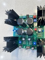
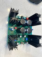
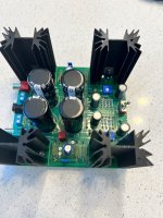
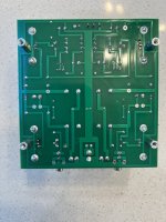
Here are some pictures. A couple notes about my build and errors I made before power on and biasing, which seemed like it went fine. I thoroughly cleaned the board, then reviewed everyhting before initial power on. I had already fixed one mistake at that point, the transistor polarity on one side of the board I had to desolder and resolder to do this, I used an inexpensive desoldering tool. The transistor, did get hot. I unsoldered and chanfer direction of one of the film capacitors, as I wanted them the same direction on each channel, even though I do not think polarity matters there. But for consistency, I did it anyways. The fets. I had it in my head they were all the same, so I so I put them in as if they were. I noticed it before power on and moved them to the correct places. you can see the rework where i did that. That's about it, I think.
Attachments
OK,swapped sides, powered on, led came on then went off, power supply does not seem to be in protection. Amp will no longer power on.
Last edited:
Hmm, it is not clear.
In both tries, you should also measure the voltage between ground and one side of the connected R10 (not so important wich side).
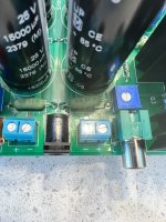
Possibly a short in the black power connector?
In both tries, you should also measure the voltage between ground and one side of the connected R10 (not so important wich side).
Possibly a short in the black power connector?
Ok, just re plugged in. The right channel is the one with R10 disconnected. Left channel reads 24V on the right channel. No LED is on at that point? Checked the connector for continuity. It is open. Thanks for the help everyone so far...
I dont understand the second part of the sentence!Left channel reads 24V on the right channel.
Now swap again connection of R10 and do the same on the right channel.
I recommend unplugging the amp and using your DMM to test for continuity for each component on each channel. Use the schematic to follow the path, marking off each confirmed trace. If you find a trace that doesn't have conductivity, you will know that component is having a problem (either reflow the solder joint or replace). Fluke has a nice explanation here: https://www.fluke.com/en-us/learn/blog/digital-multimeters/how-to-test-for-continuity
Ok, just re plugged in. The right channel is the one with R10 disconnected. Left channel reads 24V on the right channel. No LED is on at that point? Checked the connector for continuity. It is open. Thanks for the help everyone so far...
Left Channel reads 24V on both sides of the R 10 until protection kicks in. It also reads 24V on the right R10 where it is connected to the board still.
- Home
- Amplifiers
- Pass Labs
- DIY ACA mini