Worth IMHO checking continuity at said legs with rest of the circuit... doesn't look great, but who knows...
For some reason after my rework, they did not flow that well, but I get no continuity on any of those pins tested every combination of pins. Thanks for pointing that out
What temp is your soldering iron? It may be a bit low. Adding a bit of flux to the rework joint can also help it flow better. Using NP's artwork from Page 3 of his writeup (attached), you can print it and test for continuity along each PCB trace to confirm you have a good connection.
I tried to circle the pins to show where you should have continuity.

If you don't have continuity, that will be a good clue to make note of. Hang in there--troubleshooting can be frustrating.
I tried to circle the pins to show where you should have continuity.
If you don't have continuity, that will be a good clue to make note of. Hang in there--troubleshooting can be frustrating.
Attachments
Was refering to conituity with the components they are supposed to be connected to, not between legs...
Chris Jones KS just explained it better than I did 🙂
Chris Jones KS just explained it better than I did 🙂
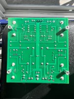
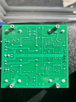
OK, I just re flowed the 2 fets, and the film cap. Fairly happy with them now. Here are the results before, and are the same as after flowing as well
Blue, continuity
Purple, continuity
Orange, no continuity, getting a resistance reading?
Blue, continuity
Purple, continuity
Orange, no continuity, getting a resistance reading?

Orange, no continuity, getting a resistance reading?
- How much resistance did you read? That's the variable resistor, so some is to be expected.
- How does the continuity on the rest of the board check out?
- Can you adjust the temperature on your soldering iron?
- What kind of solder do you use?
- What kind of tip is on your soldering iron?
- On the side that pulsed earlier, did you plug in the power supply and immediately turn it on? Mine does best if I wait for a 5 seconds, or so. If I flip the switch too quick, it will pulse and I just have to turn it back off, wait, and turn it back on.
- How much resistance did you read? That's the variable resistor, so some is to be expected. 113ohms and starts climbing.
- How does the continuity on the rest of the board check out? I have not traced the whole board yet, but I am having a problem with it going into protection, if I had an open circuit somewhere would it actually do that, or would it just not work ?
- Can you adjust the temperature on your soldering iron? Yes, it's all the way up. Model is here: https://www.parts-express.com/Stahl...perature-Soldering-Station-374-100?quantity=1
- What kind of solder do you use? It's Cardas Quad Eutectic with rosin core, on the heatsink, I used a more traditional old leaded
- What kind of tip is on your soldering iron? the tip is pretty thin, it is tinned well, shining bright when cleaned
- On the side that pulsed earlier, did you plug in the power supply and immediately turn it on? I did, Mine does best if I wait for a 5 seconds, or so. If I flip the switch too quick, it will pulse and I just have to turn it back off, wait, and turn it back on.hmm
Man, I was pretty happy with my work, until I blew it up. This was the board before biasing. I am just trying to regain a bit of credibiltiy. I have been soldering for 30 years on and off haha!
Attachments

Just to make sure...
When checking continuity here, the unit is unplugged from its PS....
You have just your unit, without its SMPS, and a multimeter set on reading R automaticaly (or so) and you use 2 pins to measure R between the points you want to measure... right?
Sorry, is quite obvious, but reading the above I just wanted to make sure...
Shouldn't orange be 0 (or so) if aiming at the very next legs of the variable resistor directly?
Just to make sure...
When checking continuity here, the unit is unplugged from its PS....
You have just your unit, without its SMPS, and a multimeter set on reading R automaticaly (or so) and you use 2 pins to measure R between the points you want to measure... right?
Sorry, is quite obvious, but reading the above I just wanted to make sure...
Yes, unplugged.
Hey, @St. Peter(sburg): for the side where the SMPS entered protection mode, do you want to try it again? This time, before turning it on, plug in the SMPS and wait 5-10 seconds to allow the caps to charge. If this works, will it play music on that side? I'll keep my fingers crossed that it does!
If that doesn't work and you have good solder joints, that may help the smarter people determine where the damage is located.
Note for after your amp is fixed: when the SMPS is plugged in and the switch is off, the amp will still thump if you plug/unplug the input cables. To avoid this, I unplug the SMPS and wait for it to fully discharge before messing with the connections.
since i use ACA mini just at work with weak Ipod as source (it has not 2V signal Voltage swing), i wonder if i can rise the gain of ACA mini? I found a hint, tweaking R5, but would be happy if someone confirms it as the way to go.
all best
stefan

all best
stefan
I know I am somewhat persistant on that, but...
Shouldn't "orange" check be 0R (or negligeable resistance) if aiming at the very next legs of the variable resistor directly?
If so, and it is showing 113R, wouldn't that indicate that possibly one of the ciruit trace from tha transistor is damaged... and a simple fix be just to solder a wire in parallel between said transistor leg and the variable resistor leg?
Not saying it would be the only damage nor the transistor would be intact, but step by step perhaos...
Just thinking out loud, and of course assuming all care had been taken re "swich on" procedure to avoid SMPS hi-cup mode...
Claude
Update. Last night, after some continuity checks and solder pad reworks and cleaning. I decided to solder back in the R10 leg. I put it down for the night. this am I connected the smps, but did not turn it on for a minute or two based on Chris's recommendation. Well, when I did the whole thing came on, at 9:02 and is still on now. I am reading voltages at the bias points that make sense and are in range. Thinking I leave it one foe a while, tweak the bias and test in my system. Right now, my VB is .200 and my VO is 15.5 on bolth sides give or take. Thanks for the support so far all.
Try to keep V0 between 11.4 to 11.6. V0 lowers when you turn P2 up (or P1 down).Right now, my VB is .200 and my VO is 15.5 on bolth sides give or take. Thanks for the support so far all.
I can't wait to see if you got it working! Congratulations!
- Home
- Amplifiers
- Pass Labs
- DIY ACA mini