Yes @Vunce plan is to add a Grayhill 2/3 sources selector switch as I have a Soekris dac and a DIY turntable with the Schiit phonostage. Transformer is the same like Antek 120v just that I used my spare sheet metal casing to keep the rest of the AC wiring away from the preamp board.

Great news! Thanks for the heads up👍@rolotube, others who want a PCB. I just placed an order for 10. Should have them in a couple of weeks.
Monday evening and Sunday afternoon was spent dissassembling the TV station amplifier only to find that the heat sink was not usable in its current form. It has a rough finish everywhere except where the RF power transistors were attached, and they were in machined pockets too small for TO247's.
Yesterday I tried to put some SiC J-fets in the high powered board in the output device position. I could not get then to work without changing some component values, and I didn't have much time, so I abandoned the idea, at least for now.
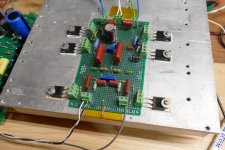
Last night and this morning's more ambitious idea was to fix the heat issue by ripping apart my breadboard and adapting it to use two parallel mosfets per channel. When I fired it up this morning I was met with high powered oscillations at about 1 MHz. There was so much RF in the air that my cheapie DVM read random numbers on the 600 volt scale with its probes lying on the bench and my old vacuum tube Knight Kit power supply that feeds the SCG board would start putting out random voltages in the 100 to 300 volt range depending on where my hands were in the air above the board.
Much of this was cured by putting jumpers across the source resistors. I had run out of the Dale 1 ohm 2 watt 1% resistors that I usually use, so I used some half ohm unknown resistors that are probably wirewound.
With those resistors bypassed there was still some oscillation present, but it was tame enough to see 40 watts per channel at the onset of clipping on 300 volts and mosfet temps around 65C after 20 minutes or so at idle with the upside down (too hot) heat sink.
I think the next step is to clean up the breadboard routing or build a new one.
Yesterday I tried to put some SiC J-fets in the high powered board in the output device position. I could not get then to work without changing some component values, and I didn't have much time, so I abandoned the idea, at least for now.
Last night and this morning's more ambitious idea was to fix the heat issue by ripping apart my breadboard and adapting it to use two parallel mosfets per channel. When I fired it up this morning I was met with high powered oscillations at about 1 MHz. There was so much RF in the air that my cheapie DVM read random numbers on the 600 volt scale with its probes lying on the bench and my old vacuum tube Knight Kit power supply that feeds the SCG board would start putting out random voltages in the 100 to 300 volt range depending on where my hands were in the air above the board.
Much of this was cured by putting jumpers across the source resistors. I had run out of the Dale 1 ohm 2 watt 1% resistors that I usually use, so I used some half ohm unknown resistors that are probably wirewound.
With those resistors bypassed there was still some oscillation present, but it was tame enough to see 40 watts per channel at the onset of clipping on 300 volts and mosfet temps around 65C after 20 minutes or so at idle with the upside down (too hot) heat sink.
I think the next step is to clean up the breadboard routing or build a new one.
Attachments
I know there is a thread on oscillations, but how do you know they are happening? Watching it on the scope? This is a general question. How do you watch for oscillations?
I love the breadboarding technique. On that particular breadboard, the points aren’t connected in a pattern, right? So, how do you connect them? Beneath the pcb? I have done it that way.
Those insulator pads are thick!!!
I love the breadboarding technique. On that particular breadboard, the points aren’t connected in a pattern, right? So, how do you connect them? Beneath the pcb? I have done it that way.
Those insulator pads are thick!!!
Good afternoon, ra7,
I am assuming that the 220R gate stopper resistors value is not critical?
I have a number of 300R Caddocks and Z foils I used as grid stoppers.
Would this make any difference?
I am assuming that the 220R gate stopper resistors value is not critical?
I have a number of 300R Caddocks and Z foils I used as grid stoppers.
Would this make any difference?
The insulators are solid alumina which is quite brittle. Thin stuff will shatter.
Oscillations are obvious sometimes, and obscure and hard to find in other times. This was probably one of the most blatant, obvious cases I have seen in a while. The scope wired directly across the speaker leads went bonkers with anything from 10 volt P-P sawtooth waves at about 1 MHz, to random "confetti" filling most of the screen. Waving my hands above the board without touching it made the idle current change. An unconnected DVM near the amp read -400 volts which changed whenever you moved near the board.
Sometimes things are not so obvious especially with higher frequency oscillations that will not make it through the OPT.
As it stands now after bypassing the source resistors and messing with the grounds and wire dress I have it down to a minimum, but it's still visible on the scope in the zero crossing areas of the sine wave as the amp is pushed into clipping. Worst case is usually the transition from one output device to the other in a class AB push pull amp.
In the past I sometimes found "invisible" oscillations with a portable AM radio or analog TV set tuned to a weak station. If either misbehaved as you ran your hands over the tubes and other non conductive surfaces, it's a sure bet that something is oscillating somewhere. I have built tube amps that wiped out a dozen or more channels on every TV in the house back in the OTA analog TV days. Modern digital TVs are far more immune to such interference and don't make good detectors. I have an RF spectrum analyzer for sure fire testing, but I didn't need it today.
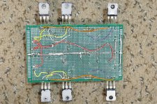
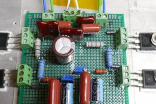
Connections on the breadboard are made with component leads or thin hookup wire. I'll flip it over and take a picture the next time it's off the heat sink.
There are lots of pictures of this kind of prototyping including some of mine and some that are far better than mine in this thread:
https://www.diyaudio.com/community/threads/post-pictures-of-your-vero-board-designs-here.171407/
Oscillations are obvious sometimes, and obscure and hard to find in other times. This was probably one of the most blatant, obvious cases I have seen in a while. The scope wired directly across the speaker leads went bonkers with anything from 10 volt P-P sawtooth waves at about 1 MHz, to random "confetti" filling most of the screen. Waving my hands above the board without touching it made the idle current change. An unconnected DVM near the amp read -400 volts which changed whenever you moved near the board.
Sometimes things are not so obvious especially with higher frequency oscillations that will not make it through the OPT.
As it stands now after bypassing the source resistors and messing with the grounds and wire dress I have it down to a minimum, but it's still visible on the scope in the zero crossing areas of the sine wave as the amp is pushed into clipping. Worst case is usually the transition from one output device to the other in a class AB push pull amp.
In the past I sometimes found "invisible" oscillations with a portable AM radio or analog TV set tuned to a weak station. If either misbehaved as you ran your hands over the tubes and other non conductive surfaces, it's a sure bet that something is oscillating somewhere. I have built tube amps that wiped out a dozen or more channels on every TV in the house back in the OTA analog TV days. Modern digital TVs are far more immune to such interference and don't make good detectors. I have an RF spectrum analyzer for sure fire testing, but I didn't need it today.
Connections on the breadboard are made with component leads or thin hookup wire. I'll flip it over and take a picture the next time it's off the heat sink.
There are lots of pictures of this kind of prototyping including some of mine and some that are far better than mine in this thread:
https://www.diyaudio.com/community/threads/post-pictures-of-your-vero-board-designs-here.171407/
Attachments

Last edited:
Hi George, could you share the reasons of your choice in depletion parts for the gain device of the fetset and what disadvantages you'd expect when an enhancement part is used there?Yesterday I tried to put some SiC J-fets in the high powered board ...
There are several reasons for choosing the IXTH6N100D2 part for the gain device, but the main one is SOA.
The UNSET technology started out with vacuum tube technology. I was looking for a way to get triode curves from cheap TV line output pentodes, 300B sound without the 300B price.
The depletion mosfet is the closest silicon device to a vacuum tube in it's operating characteristics. I had simply stuck a pair of LND150 mosfets right into the tube socket in a vacuum tube guitar amp maybe 10 years ago to see what would happen and being quite surprised to see that it worked.
I had some IXTH6N100D2 parts on hand from a solid state high voltage power supply project that never got finished. The choice of the IXTH6N100D2 for the power supply is the same reason that I chose it for the first FETSET.
Mosfet designers optimize their products to fit a market need. Nearly all of the high voltage mosfets in existence are designed for fast switching and optimized for low loss in switching (SMPS) applications. They are NOT designed to operate continuously in the linear region. There are mosfets designed for audio and other linear operating modes, but most top out at 200 volts or so. A single ended amp like this that directly drives an output transformer will see about TWICE the B+ voltage across the device in normal operation due to the magnetic storage effects in the OPT. Voltages can go considerably higher if the amp is driven into hard clipping with a reactive load as seen in a guitar amp operating near the speaker's resonant frequency. I am currently running about 300 volts of B+.
It is now known that mosfets exhibit a secondary breakdown effect similar to that seen in BJT's, but by a slightly different mechanism. Some semiconductor manufacturers still do not note this in their data sheets. If the DC SOA curves in the data sheet seem to line up exactly with the devices maximum rated dissipation (On Semi / Fairchild) do NOT trust the parts to work reliably even well within their published specs, I have blown up enough of them to know this. The same is true if the curves show no DC spec. Some ST parts stop at 10 mS. Idle is worse case in a class A SE amp, and most of our amps will see idle conditions for more than 10 mS.
When designing the power supply I searched for mosfets that were specified for operation in the linear region that were capable of continuous dissipation in the 100 watt+ range. the IXYS depletion mode (D and D2 suffix) devices and the IXYS Linear series enhancement mode devices (L and L2 suffix) were my first choices, so I got a few to play with. The IXTH6N100D2 is specified for "800 volts at 225 mA" and the IXTH15N50L2 (enhancement device) is rated for "400 volts at 375 mA" but I have not tried it yet as different bias conditions will be required. The IXTH6N100D2 was the cheapest part, so it got the hot seat first, and I haven't blown one yet.
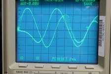
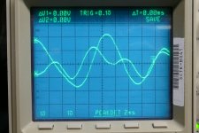
I stated that I would post a picture of the back side of the proto board, so here it is, photographed during yesterday's modification session. The oscillation still persists, though it's now tame enough that I can play music through it, and crank it to the 40 WPC level without blowing any parts. The second picture shows a burst of oscillation that pops up on a bass guitar solo that is putting about 40 volts peak to peak across my speakers. Today's experiments will involve the gate stopper resistors and some "magic (ferrite) beads." Unlike Bybee purifiers and Shakti stones, these actually do something.
The UNSET technology started out with vacuum tube technology. I was looking for a way to get triode curves from cheap TV line output pentodes, 300B sound without the 300B price.
The depletion mosfet is the closest silicon device to a vacuum tube in it's operating characteristics. I had simply stuck a pair of LND150 mosfets right into the tube socket in a vacuum tube guitar amp maybe 10 years ago to see what would happen and being quite surprised to see that it worked.
I had some IXTH6N100D2 parts on hand from a solid state high voltage power supply project that never got finished. The choice of the IXTH6N100D2 for the power supply is the same reason that I chose it for the first FETSET.
Mosfet designers optimize their products to fit a market need. Nearly all of the high voltage mosfets in existence are designed for fast switching and optimized for low loss in switching (SMPS) applications. They are NOT designed to operate continuously in the linear region. There are mosfets designed for audio and other linear operating modes, but most top out at 200 volts or so. A single ended amp like this that directly drives an output transformer will see about TWICE the B+ voltage across the device in normal operation due to the magnetic storage effects in the OPT. Voltages can go considerably higher if the amp is driven into hard clipping with a reactive load as seen in a guitar amp operating near the speaker's resonant frequency. I am currently running about 300 volts of B+.
It is now known that mosfets exhibit a secondary breakdown effect similar to that seen in BJT's, but by a slightly different mechanism. Some semiconductor manufacturers still do not note this in their data sheets. If the DC SOA curves in the data sheet seem to line up exactly with the devices maximum rated dissipation (On Semi / Fairchild) do NOT trust the parts to work reliably even well within their published specs, I have blown up enough of them to know this. The same is true if the curves show no DC spec. Some ST parts stop at 10 mS. Idle is worse case in a class A SE amp, and most of our amps will see idle conditions for more than 10 mS.
When designing the power supply I searched for mosfets that were specified for operation in the linear region that were capable of continuous dissipation in the 100 watt+ range. the IXYS depletion mode (D and D2 suffix) devices and the IXYS Linear series enhancement mode devices (L and L2 suffix) were my first choices, so I got a few to play with. The IXTH6N100D2 is specified for "800 volts at 225 mA" and the IXTH15N50L2 (enhancement device) is rated for "400 volts at 375 mA" but I have not tried it yet as different bias conditions will be required. The IXTH6N100D2 was the cheapest part, so it got the hot seat first, and I haven't blown one yet.
I stated that I would post a picture of the back side of the proto board, so here it is, photographed during yesterday's modification session. The oscillation still persists, though it's now tame enough that I can play music through it, and crank it to the 40 WPC level without blowing any parts. The second picture shows a burst of oscillation that pops up on a bass guitar solo that is putting about 40 volts peak to peak across my speakers. Today's experiments will involve the gate stopper resistors and some "magic (ferrite) beads." Unlike Bybee purifiers and Shakti stones, these actually do something.
Attachments
Sorry for the late reply. Yeah, that would work just fine. Anything from 33R to 770R should be fine.Good afternoon, ra7,
I am assuming that the 220R gate stopper resistors value is not critical?
I have a number of 300R Caddocks and Z foils I used as grid stoppers.
Would this make any difference?
With all due respect, it is unlikely that Bybee devices don't do anything. More likely that everyone who tried to measure what they do made incorrect assumptions about what they should be checking for by way of measurements. Same thing to some extent with ferrite beads. The manufacturers of ferrites tell you about the benefits of the their products, but leave it up to you to find out if there are any problems for your particular application. Bruno Putzeys investigated the effects of ferrites used in the output inductors of his Purify class-D amplifiers. What he found was hysteresis noise/distortion: https://purifi-audio.com/2020/04/28/dist/#:~:text=Unlike most forms of distortion,a hysteretic mechanism at work.Unlike Bybee purifiers and Shakti stones, these actually do something.
Based on multiple interviews with John Curl about Bybee devices and interviews with some other people who had some experience with them, so far as I can tell Bybee devices must produce signal-correlated noise/distortion more or less analogous to what ferrites can do. Different device and apparently somewhat different physics of course.
John Curl's first experience hearing the effects of a Bybee device was when he inserted a Bybee in series with the AC line hot of an Vendetta preamp. At the time this occurred it was not common for such audio devices to include AC line EMI/RFI noise filters. Apparently the Bybee introduced something of that nature into the preamp where it then affected the sound. The mechanisms by which EMI/RFI can produce signal correlated noise through demodulaton/remodulation in semiconductor junctions are pretty well understood. Modern opamps of recent design are specified for immunity to such effects, even if the specification is not listed in the datasheet.
There are a couple of ways to look for signal-correlated noise using FFT measurements, but of course none of the Bybee critics knew how or else they didn't bother to check. Depending on the degree of correlation of the noise with the audio signal, the absence or presence of a test tone may show a shift in the noise floor. The shift may look small if the noise energy is distributed across all FFT bins, but the ear is particularly sensitive to such noise ('exquisitely sensitive,' according to ESS, the dac chip manufacturer). When the noise/distortion is more closely correlated with the test tone, then the noise may be seen in a very high resolution FFT. It appears as widening of the noise skirts around the base of the test tone spectral line.
Regarding Shakti Stones, I won't argue 🙂
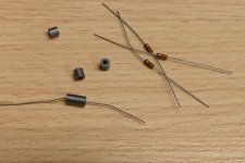
There are lots of things called "ferrites" each with some widely different properties. We had a lot of different choices in cell phone and high powered RF transmitter design. My "magic beads" are from a big bag of unknown ferrites I got at a surplus auction maybe 25 years ago. They do seem useful as "RF chokes" in the 1 to 20 MHz range, as tested on an RF network analyzer.
I really shouldn't pick on either of the easy targets since I have never actually seen them. I did see a thread somewhere many years ago where someone took a Bybee apart and it looked much like a carbon resistor encased in epoxy. Maybe it also included some kind or ferrite material, I don't know. At the time they were rather pricey, around $100 each, I think.
My oscillating amp had one 220 ohm stopper resistor shared between two mosfets, not exactly ideal. After a general layout clean up including snubbers on the OPT primary and better B+ bypassing, the full on radio transmitter stuff was gone, but the random bursts were still present. I have dealt with these before when using mosfets to directly drive vacuum tubes, so I busted out the "magic beads."
In mild cases I generally put a bead on each lead of the stopper resistor. I bad cases a bead goes on the non common leads of the mosfets as well. larger beads go on the plate leads of the output tubes. In this space constrained build my first attack was to stuff a 330 ohm 1/8 watt carbon composition resistor inside two beads. A DIY Bybee? I put one of these right at the "socket" pin for the gate of each output mosfet.
In this case that cured all of the oscillation. The picture shows the same piece of music cranked to the edge of clipping, but I couldn't capture the exact same musical moment just by pushing the "store" button on my 30 year old TEK scope. I saw no ugliness in 4 plays of this song at different volume levels. All levels had random bursts yesterday.
The board has been removed and replaced 4 times since I properly applied thermal goop so I didn't run it at full power for long. I'll redo the goop and take some measurements later today, or tomorrow.
Then, I gotta build me one of these for real........
Attachments
Thanks Rick! I am on business travel for the first time since January 2020 when Wuhan was starting to get into the news. Boy, even thinking about it is traumatic.
I never thought we would be talking about Bybee purifiers and Shakti stones in this thread
I need to get my low voltage-high current FETSET going. The chassisyhas been ready for a while, just need to find the time.
I never thought we would be talking about Bybee purifiers and Shakti stones in this thread
I need to get my low voltage-high current FETSET going. The chassisyhas been ready for a while, just need to find the time.
I remember the reveal Tubelab recalls of the BYBEE device and even though I know the maker is not a BS artist I have never spent the money to hear for myself what they do or do not do.
I remember when Jackinnj did his famous regulator test in LINEAR AUDIO and included this device. Needless to say my memory tells me they did nothing but then they were never marketed as a regulator.
Maybe they are akin to the Swedish sandbox grounding device. Far more affordable than that!
Same with the SHAKTI stone - I figure if these things worked as well as we wish they did tthere would be more people talking about them. I love tweaks and am willing to give them a try as long as they are DIY - but these PET ROCK style devices remind me of that great old joke about the tuna fish that was for selling not for eating ...
I have been known to sprinkle crystals on my computer mother board. Did I hear any improvement? NO, but just in case I missed hearing the improvement I leave them there until they fall off when I forget they are there and pick up the motherboard.
In case there are others out there as mindless as I - and to prove, once again, the deceptive power of the printed word:
So I am doing the first stage of testing the SCG board.
I test the "left" side first and place the probe on the TP under where TP1 is printed - all is well.
I go the other channel and place the probe where TP1 is printed and there is no voltage. OH NO what have I done? I place the probe on the other side and there is voltage. OH NO I really did something strange!
Eventually I see by looking at the traces that the markings have nothing to do with where you place the probe. Of course it is obvious but so easy to be mislead by printing.
What is funny is I looked at the board so closely since I wanted to place the gate stoppers at the devices but I never looked up there at all. The dangers of assumptions ...
I asked about the resistors when I discovered that the carbon film resistors I bought for these positions is SUPER MAGNETIC. I cannot have magnetic resistors in ra7's line stage! It would be a sacrilege.
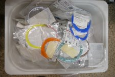
I got a huge bin full of "Teflon covered silver plated stranded copper wire" for like $10 because it stuck to a magnet. All is pre cut and stripped in individual military packaging with FSNs (Federal Stock Numbers) which do state Teflon silver and copper. That is the colored hookup wire I used to wire up my breadboard, and virtually everything that I have built for the past 25 years or so. Quite a few of my resistors are also magnetic.
This might be a problem in a phono stage where signal levels are in the few millivolt range but shouldn't matter much in an amp where tens to hundreds of volts of signal are present.
This might be a problem in a phono stage where signal levels are in the few millivolt range but shouldn't matter much in an amp where tens to hundreds of volts of signal are present.
Attachments
IIRC it was Scott Wurcer who bought a Bybee and proceeded to show that every advertising claim on Bybee's website was a not true. He then proceeded to take the device apart and found nothing he thought could affect sound. The one thing he made no effort to do was to see by careful and thorough measurement if it did anything at all. Seemed like he only wanted to debunk the far out advertising puffery. Nobody who has heard Bybee devices says they sound like the advertising claims. Just like I hope no one who buys Wheaties breakfast cereal believes it will turn them into a champion athlete.
BTW, the reason I responded to the commentary about Bybee devices is because of what happened to John Curl when he told the truth about Bybees affecting sound. People tried to measure Bybees for HD and for resistance. Not finding either effort fruitful they proceeded to try to destroy John's reputation. At best those people jumped to conclusions with way too much overconfidence that if no HD then no audible effect was possible. Wurcer was smart enough he probably could have figured it out, if he were not on some vendetta to prove the advertising puffery false. Again, John Curl had his reputation badly damaged from telling the truth. Something is wrong when people are hurt like that just for being honest.
BTW, the reason I responded to the commentary about Bybee devices is because of what happened to John Curl when he told the truth about Bybees affecting sound. People tried to measure Bybees for HD and for resistance. Not finding either effort fruitful they proceeded to try to destroy John's reputation. At best those people jumped to conclusions with way too much overconfidence that if no HD then no audible effect was possible. Wurcer was smart enough he probably could have figured it out, if he were not on some vendetta to prove the advertising puffery false. Again, John Curl had his reputation badly damaged from telling the truth. Something is wrong when people are hurt like that just for being honest.
Last edited:
It happens here too often - the banning of those who simply tell the truth.
A very good man and dedicated audiophile who happens to find "clocks" his favorite pursuit and a "devotee" of the sadly departed Pat di Giacomo who with great humor went by the moniker of JOCKO HOMO was banned from this site because he called into question the design pf a dac of which I have bought two and have since disposed of them since they were not fully developed devices. The irony is Pat was banned many years ago and could be boisterous - this other fellow was always more of a gentleman than I could ever be.
The thought of someone being able to damage John Curl's reputation is sickening in the extreme. A man in the Pantheon of audio.
I would have to say if Mr. Wurcer thinks something is BS it is BS. I have never found him, sad to say he no longer participates here, to say anything controversial for the sake of controversy and his career and work are beyond doubt.
It is an aesthetic thing for me not wanting magnetic resistors in the circuit. I readily admit I have never compared the sound of a magnetic resistor to one that is not magnetic.
One great thing about the PASS FORUM is I do not believe any serious person has ever been banned for saying something here. A true free speech zone.
- Home
- Amplifiers
- Pass Labs
- Schade Common Gate (SCG) Preamp