1. Does PSUD compensate for the warmup time of the load on the B+ ?
Example, start with a cold 6L6, EL34, or KT88 as the cathode comes to final temperature?
Zero current at power-up, finally reaching the amplifier's designed quiescent current.
The load on the power supply varies at the same time the power supply caps are charging to final voltage.
If it does not include the slow and non linear increase of output tube current at power-up, then it needs to.
Otherwise, all those fancy graphs are just a simulation.
2. "the spec, 350V-0-350Vrms is the voltage when the rated dc milliamperes flow thru a resistor load" ? ? ?
What kind of rectifier?
Full Wave Silicon diodes using the center tap?
What filtering after the rectifier?
A. No filter?
B. Cap filter?
C. Choke input followed by a cap?
The maximum DC current rating of the transformer will be different for A., B., and C.
Given a fixed resistor load, the peak current, and average current will be different for A., B., and C.
So, because of the DCR of the secondary, the peak voltage from that secondary will be different for A., B., and C.
(And the DCR of the primary will also affect the peak and average voltage from the secondary too).
If you doubt about the transformer's various current ratings for A., B., and C., then look up the Hammond transformer document that discusses it.
It is a little more complex than some are aware of.
For power supplies, the Integral of I-squared x R is very important.
Some transformers run very hot when DCR and I-squared are not considered.
Kind of reminds me of Physics: Impulse Momentum, Mass x Velocity squared.
Run your car into a brick wall at 5 MPH.
Run your car into a brick wall at 10 MPH, the impulse momentum is 4 x what it was at 5 MPH.
Just saying.
Last edited:
It isn't a given. The 7591 pentode mode SE I'm building shifts its 350 vdc B+ under a couple volts during severe clipping. The power supply is 6au4gta rectified, smoothed by two 0.6H 11 ohm DCR inductors. At this point in the build residual hum at the speaker terminals is ~0.5 mv apparently due to layout.There will be a audible difference when the b+ can move 50v when compared to silicon.
From a quick analysis of the datasheet a 6AU4 adds under 70 ohms of dynamic impedance, often in line with the typical DCR of PS TX and PS smoothing inductors. Small resistances can also stabilise power supply ringing under dynamic loads. It's not as simple as tubes always bad.

"crap" High Voltage supplies are going to increase the noise present on the mains. DCDC switching noise, POE (yes your power company has Ethernet on your incoming power), WIFI etc...
When you use a SS rectifier all that crap comes into the supply. Your using high voltage caps which are great at 100-120Hz but not real good above that. All that crap goes into the circuit and effects performance. Tube rectifiers don't carry any of that.
Plus there is the startup time. Why did WE use the same warm up time on the 274 as the 300B? So there would not be any filament stripping.
Another thing is clipping. You have a hard SS supply and the clipping is going to be nasty. Use a tube and soft clipping and that is what players want.
Guys remember... just because you can do something doesn't mean it's good or right. The whole idea behind DIY is not to stick something together and say IT WORKS, BEST EVER! No--- it's well that works but can I make it better. After years and years you get a box of stuff that works better than the failures and you can then make better decisions moving forward.
For DHT the best sound I have gotten out the 1280 amps I have made that way... LCLC. First L should be large > 10H, second one low DCR, first C should be film, second can be whatever makes it sound good... Black Gate, AN whatever.
Thanks,
Gordon
When you use a SS rectifier all that crap comes into the supply. Your using high voltage caps which are great at 100-120Hz but not real good above that. All that crap goes into the circuit and effects performance. Tube rectifiers don't carry any of that.
Plus there is the startup time. Why did WE use the same warm up time on the 274 as the 300B? So there would not be any filament stripping.
Another thing is clipping. You have a hard SS supply and the clipping is going to be nasty. Use a tube and soft clipping and that is what players want.
I would never do 16 of anything. Matching dies after a week of use. Why would I put the customer through that agony? I built bass amps for people and fixed a boat load of SVT's in my day. You want a nice 70W bass amp a pair of KT88/6550 would be fine. You want more than that then a pair of KT150's but never parallel push pull. One or two 5U4 for those will do.i used a 16A 1000V flatpack bridge rectifier on my 16KT88 triode mode amplifier, the owner was so ecstatic!!!, what tube rectifiers can you use for that?
Guys remember... just because you can do something doesn't mean it's good or right. The whole idea behind DIY is not to stick something together and say IT WORKS, BEST EVER! No--- it's well that works but can I make it better. After years and years you get a box of stuff that works better than the failures and you can then make better decisions moving forward.
For DHT the best sound I have gotten out the 1280 amps I have made that way... LCLC. First L should be large > 10H, second one low DCR, first C should be film, second can be whatever makes it sound good... Black Gate, AN whatever.
Thanks,
Gordon
I try to do my best to reduce total DCR of power supply. That is low DCR of transformer windings and chokes. When I enter low DCR values in PSUD2 with 1,000 V SS diodes, with choke input, the program says diode voltage rating is exceeded at a number of milliseconds after start. If I enter series diodes, result is the same, it just takes few milliseconds more. Looking at the voltage graph, I can see very high spike at startup.
Semiconductors are destroyed with excessive voltage even for a very short time. Tube are remarkably tolerant to voltage spikes.
Semiconductors are destroyed with excessive voltage even for a very short time. Tube are remarkably tolerant to voltage spikes.
I have to ask why the power mains companies made such a bad decision about how to communicate (down the power line? Wow!).
WiFi down the power line? Really?
"Cheap is not good, and good is not cheap". Thanks to Frank Reps who built and wrote about Gordon Rankin's 2A3 "Baby Ongaku" in "Sound Practices"; his article gave that quote.
A real electronic engineer should know the difference between:
EMI, Electro Magnetic Interference (And the associated regulations).
And . . .
EMC, Electro Magnetic Compatibility.
(Many devices that pass EMI regulations are Not Compatible with each other).
How about the term for various forms of communication at 2.4GHz, and 5GHz (the term is "Interoperability", a great oxymoron).
I remember being at the 2000 Bluetooth convention in San Francisco, Calif.
I watched as perhaps over 100 Bluetooth devices were all on at the same time.
I measured the real time spectrum collisions, etc., on the 3086 Sony Tektronix Real Time spectrum analyzer.
A freeway is rated to be good at 70MPH, but then reality sets in when there is a collision. Get it?
I have a phono preamp that uses a switching power supply that plugs in (Wall Wart). If I plug it in . . .
I do not get good AM reception on a battery powered AM radio, no matter where I go in my house.
That power supply that 'passes EMC regulations' sprays hash at AM frequncies all over my house mains power wiring.
And now you are worried about my vacuum tube amplifiers spraying interference back on to the power line ? ? ?
I have to find the time to do a spectrum study of my power mains, with the amplifier turned off, and with it turned on.
Give me a chance to prove what I expect to see in the spectrum. Can you guess what I expect to see?
A few correct measurements might settle the matter.
I have been wrong before, and I can make mistakes again; I am willing to confess if I am wrong.
Just my $0.02
Last edited:
silicon rectifiers are dirt cheap, i get them for free from discarded power supply boards, so why not use them and give them a second chance....
I try to do my best to reduce total DCR of power supply. That is low DCR of transformer windings and chokes. When I enter low DCR values in PSUD2 with 1,000 V SS diodes, with choke input, the program says diode voltage rating is exceeded at a number of milliseconds after start. If I enter series diodes, result is the same, it just takes few milliseconds more. Looking at the voltage graph, I can see very high spike at startup.
Semiconductors are destroyed with excessive voltage even for a very short time. Tube are remarkably tolerant to voltage spikes.
that is why i have stayed away from full wave center tapped power supplies, for me a single secondary with the usual tube rects aided and abbetted by silicon rects....
even better is a full wave bridge used in the Marantz 9, HK Citation II 6500 pp amps and several Japanese amps like the Sansui Au-111...diy is about having lots of fun!!!!
Attachments

Perhaps 12kV diodes used in microwave ovens such as BY12 or HVM12 are better suited?... 1,000 V SS diodes, with choke input, the program says diode voltage rating is exceeded ...
Serious Series Circuit:
A transformer secondary sends 350Vrms to a solid state diode anode, diode cathode to a choke, choke out to a capacitor.
With no load on the capacitor, the voltage will be +500VDC. (no load means no bleeder resistor, and all the tube filaments and cathodes are cold / non-conducting plates and screens, which they will be when you turn on the amplifier).
When the reverse alternation comes around, there will be -500V peak on the solid state diode anode, and +500V on the diode cathode (that is 1000V reverse volts across the diode.
Then the wife turns off the washer motor . . . a big spike comes onto the 120V power line. Ouch! that poor 1000V diode is broken.
Do not attempt to use a solid state 1000V peak reverse rated diode for that 350Vrms and solid state rectifier circuit.
I bet your simulation software does not mention the wife turning off a motor, and getting a large voltage spike on the power line.
Even if the B+ has a capacitor input filter, you still have the same broken diode; no choke necessary to break the diode.
"Attention to Details" is the key to successful reliability.
Last edited:
Yup, those uW diodes are hardy, but PSUD2 version that I use has only a limited choice of rectifiers.
Who needs wife's washer with choke input supply.
Who needs wife's washer with choke input supply.
sser2,
Most wives turn all kinds of things off and on without asking the husband.
I guess you might be prejudiced against choke input filters, right?
And what is wrong with doing longhand calculations. Calculate using your own favorite diode.
Oh, I use an old HP model 11 calculator. I retired that Post Versalog slide rule in 1985.
Software and me do not get along.
Simulation . . . Ha! . . . or in Japanese, Hi!
HK's Stu Hegemann was a big fan of low DCR power transformers. In some of his designs he used voltage doubler, which enabled very low secondary DCR, something like 12 Ohms for 330 VDC B+.that is why i have stayed away from full wave center tapped power supplies, for me a single secondary with the usual tube rects aided and abbetted by silicon rects....
even better is a full wave bridge used in the Marantz 9, HK Citation II 6500 pp amps and several Japanese amps like the Sansui Au-111...diy is about having lots of fun!!!!
No, no, no. I use choke input exclusively, never capacitor input.sser2,
Most wives turn all kinds of things off and on without asking the husband.
I guess you might be prejudiced against choke input filters, right?
And what is wrong with doing longhand calculations. Calculate using your own favorite diode.
Oh, I use an old HP model 11 calculator. I retired that Post Versalog slide rule in 1985.
Software and me do not get along.
Simulation . . . Ha! . . . or in Japanese, Hi!
What I meant was that choke input supply produces tremendous turn-on spike all by itself, higher peak volt than any wife's washer.
Which gets back to why a tube rectifier is a better choice for choke input supply. Not only tolerance of tube rectifiers to voltage spikes, but slow start taming the turn-on spike.
Last edited:
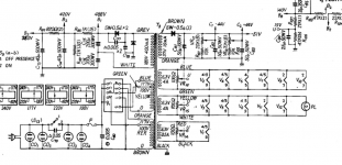
FWIW, all three B+ supplies shown in post #67 are voltage doublers rather than FW bridges. This was common in the early days of silicon rectifiers because voltage ratings were harder to come by than current ratings.
All good fortune,
Chris
All good fortune,
Chris
A B+ secondary for a voltage doubler only needs 1/2 the windings of a center tap full wave secondary.
But the center tap windings are each on only for part of one alternation;
But the single winding voltage doubler secondary is on for both part of the positive alternation, and part of the negative alternation.
The lesser turn primary for the voltage doubler has to have '2 times the wire cross section area' in order to deal with 2 x higher duty cycle of voltage doubler circuits, versus center tap circuits.
Take a 2 diode center tap circuit that drives a 100uF cap.
Compare a 2 diode voltage doubler, it needs two 200uF caps to get the same final 100uF filtering; versus the single 100uF full wave cap.
Yes, the 100uF cap has to have 2 x the voltage rating of the doubler caps.
Tradeoffs abound.
Yes, and Fun Fact, each of these three common choices requires the same PIV x Ipk total.
All good fortune,
Chris
All good fortune,
Chris
1. Does PSUD compensate for the warmup time of the load on the B+ ?
You really should give the software a try. It's an incredibly useful tool. To answer your question take a look at the options.
Although the technical aspects are over my head I've been kinda sorta following this thread to the best of my abilities.
On my current breadboard project I'm using a version of the "cockeyed bridge" that Eli Duttman promoted fairly often here on DIY and also at AA. Part SS and part tube using a 6AX4GTB for slow start.

I'd be interested in any comments about such a design and how it compares to others being discussed.
Also, I've used PSUD for basic voltage predictions but not much beyond that. I'm guessing that it is not able to simulate the design I'm using. Or can it?
On my current breadboard project I'm using a version of the "cockeyed bridge" that Eli Duttman promoted fairly often here on DIY and also at AA. Part SS and part tube using a 6AX4GTB for slow start.
I'd be interested in any comments about such a design and how it compares to others being discussed.
Also, I've used PSUD for basic voltage predictions but not much beyond that. I'm guessing that it is not able to simulate the design I'm using. Or can it?
- Home
- Amplifiers
- Tubes / Valves
- Solid state versus tube rectifiers in a PSU